
Circuit Documentation
Summary
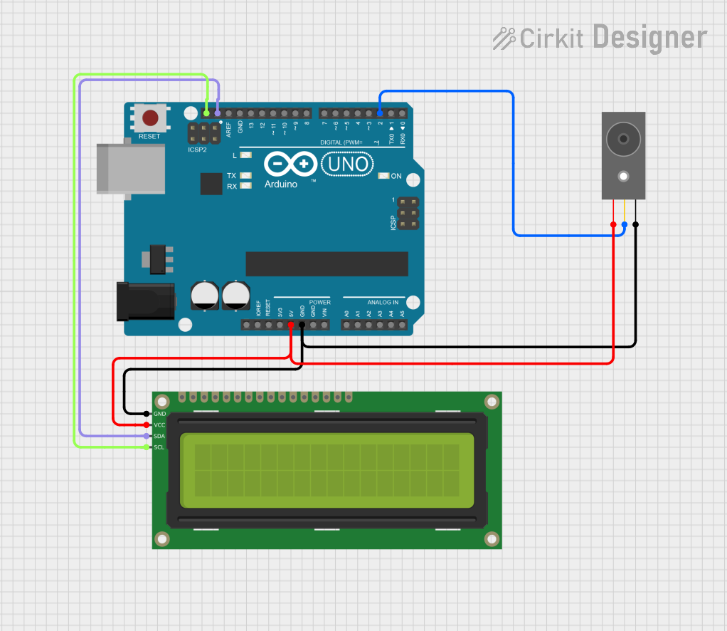
This circuit utilizes an Arduino UNO microcontroller to monitor an IR Break Beam Sensor. The sensor detects interruptions in a beam and communicates its state to the Arduino. The Arduino processes this information and displays the status on a 16x2 I2C LCD. When the beam is intact, the LCD shows "Beam Intact," and when the beam is broken, it displays "Beam Broken." This setup is ideal for applications requiring object detection or presence sensing.
Component List
Arduino UNO
- Description: A microcontroller board based on the ATmega328P. It is used for programming and controlling the circuit.
- Purpose: Acts as the central processing unit, reading inputs from the IR Break Beam Sensor and controlling the output to the LCD.
IR Break Beam Sensor
- Description: A sensor that detects interruptions in a beam of infrared light.
- Purpose: Provides a digital output signal to the Arduino when the beam is broken.
16x2 I2C LCD
- Description: A liquid crystal display that can show 16 characters on 2 lines, controlled via I2C communication.
- Purpose: Displays the status of the beam (intact or broken) as determined by the Arduino.
Wiring Details
Arduino UNO
5V: Connected to the V+ pin of the IR Break Beam Sensor and the VCC pin of the 16x2 I2C LCD.
GND: Connected to the GND pin of the IR Break Beam Sensor and the GND pin of the 16x2 I2C LCD.
SCL: Connected to the SCL pin of the 16x2 I2C LCD.
SDA: Connected to the SDA pin of the 16x2 I2C LCD.
D2: Connected to the OUT pin of the IR Break Beam Sensor.
Documented Code
/*
  This Arduino Sketch monitors an IR Break Beam Sensor connected to pin D2.
  It displays "Beam Intact" on a 16x2 I2C LCD when the beam is not broken and
  "Beam Broken" when the beam is interrupted. The status is updated on the LCD.
*/

#include <Wire.h>
#include <LiquidCrystal_I2C.h>

const int sensorPin = 2; // Pin connected to the sensor's OUT pin
int sensorState = 0;     // Variable to store the sensor state

// Set the LCD address to 0x27 for a 16 chars and 2 line display
LiquidCrystal_I2C lcd(0x27, 16, 2);

void setup() {
  pinMode(sensorPin, INPUT); // Set the sensor pin as an input
  lcd.begin(16,2);           // Initialize the LCD
  lcd.backlight();           // Turn on the backlight
}

void loop() {
  sensorState = digitalRead(sensorPin); // Read the sensor state

  lcd.clear(); // Clear the previous message

  if (sensorState == HIGH) {
    lcd.setCursor(0, 0); // Set cursor to first line
    lcd.print("Beam Intact"); // Display if the beam is intact
  } else {
    lcd.setCursor(0, 0); // Set cursor to first line
    lcd.print("Beam Broken"); // Display if the beam is broken
  }

  delay(500); // Wait for half a second before checking again
}
This documentation provides a comprehensive overview of the circuit, detailing the components used, their wiring, and the code that drives the functionality of the system.