Cirkit Designer
Your all-in-one circuit design IDE
Home /
Project Documentation
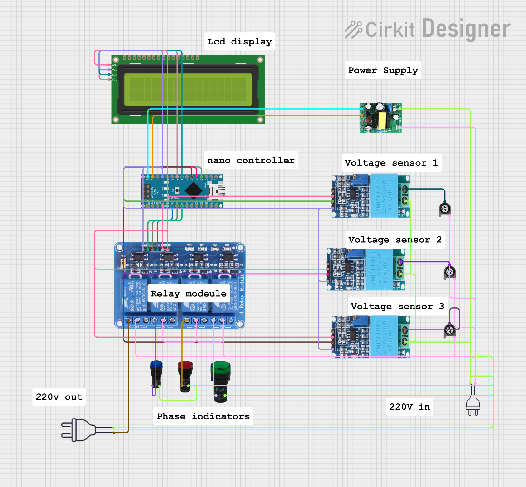
Arduino Nano-Based Smart Power Monitoring and Control System with I2C LCD Display
Circuit Documentation
Summary
This circuit involves an Arduino Nano microcontroller interfacing with various components including a 16x2 I2C LCD, multiple ZMPT101B voltage sensors, a 4-channel relay module, pilot lamps, and a power supply unit. The Arduino Nano controls the relays and reads data from the voltage sensors, displaying relevant information on the LCD. The circuit is powered by an AC-DC PSU board that converts 220V AC to 5V and 12V DC.
Component List
Arduino Nano
- Description: A small, complete, and breadboard-friendly board based on the ATmega328P.
- Pins: D1/TX, D0/RX, RESET, GND, D2, D3, D4, D5, D6, D7, D8, D9, D10, D11/MOSI, D12/MISO, VIN, 5V, A7, A6, A5, A4, A3, A2, A1, A0, AREF, 3V3, D13/SCK
16x2 I2C LCD
- Description: A 16x2 character LCD display with I2C interface.
- Pins: GND, VCC, SDA, SCL
ZMPT101B
- Description: A voltage sensor module for AC voltage measurement.
- Pins: OUT, GND, VCC, NEUTRO, FASE
Relay 4 Channel 5v
- Description: A 4-channel relay module for controlling high voltage devices.
- Pins: GND, IN1, IN2, IN3, IN4, VCC, COM1, COM2, COM3, COM4, NO1, NO2, NO3, NO4, NC1, NC2, NC3, NC4
Pilot Lamp Blue
- Description: A blue pilot lamp for indicating status.
- Pins: x1, x2
Pilot Lamp Red
- Description: A red pilot lamp for indicating status.
- Pins: X1, X2
Pilot Lamp Green
- Description: A green pilot lamp for indicating status.
- Pins: X1, X2
Power 220v
- Description: A 220V AC power source.
- Pins: hot wire, neutral wire
AC-DC PSU board 220V-5V&12V
- Description: A power supply unit that converts 220V AC to 5V and 12V DC.
- Pins: AC-N, AC-L, +5V, GND, +12V
Trimmer Potentiometer
- Description: A variable resistor used for adjusting voltage levels.
- Pins: leg1, wiper, leg2
- Properties: Resistance: 10000 Ohms
Wiring Details
Arduino Nano
- GND: Connected to GND of ZMPT101B (3 units), 16x2 I2C LCD, Relay 4 Channel 5v, and AC-DC PSU board.
- D2: Connected to IN1 of Relay 4 Channel 5v.
- D3: Connected to IN2 of Relay 4 Channel 5v.
- D4: Connected to IN3 of Relay 4 Channel 5v.
- D5: Connected to IN4 of Relay 4 Channel 5v.
- VIN: Connected to +5V of AC-DC PSU board.
- 5V: Connected to VCC of ZMPT101B (3 units), 16x2 I2C LCD, and Relay 4 Channel 5v.
- A5: Connected to SCL of 16x2 I2C LCD.
- A4: Connected to SDA of 16x2 I2C LCD.
- A2: Connected to OUT of ZMPT101B.
- A1: Connected to OUT of ZMPT101B.
- A0: Connected to OUT of ZMPT101B.
16x2 I2C LCD
- GND: Connected to GND of Arduino Nano.
- VCC: Connected to 5V of Arduino Nano.
- SDA: Connected to A4 of Arduino Nano.
- SCL: Connected to A5 of Arduino Nano.
ZMPT101B
- GND: Connected to GND of Arduino Nano.
- VCC: Connected to 5V of Arduino Nano.
- OUT: Connected to A2, A1, and A0 of Arduino Nano.
- NEUTRO: Connected to neutral wire of power 220v, Pilot Lamp Green, Pilot Lamp Blue, Pilot Lamp Red, and AC-N of AC-DC PSU board.
- FASE: Connected to wiper of Trimmer Potentiometer.
Relay 4 Channel 5v
- GND: Connected to GND of Arduino Nano.
- IN1: Connected to D2 of Arduino Nano.
- IN2: Connected to D3 of Arduino Nano.
- IN3: Connected to D4 of Arduino Nano.
- IN4: Connected to D5 of Arduino Nano.
- VCC: Connected to 5V of Arduino Nano.
- COM1, COM2, COM3, COM4: Connected to leg2 of Trimmer Potentiometer and hot wire of power 220v.
- NO1: Connected to X1 of Pilot Lamp Green.
- NO2: Connected to X1 of Pilot Lamp Red.
- NO3: Connected to x1 of Pilot Lamp Blue.
- NO4: Connected to hot wire of power 220v.
Pilot Lamp Blue
- x1: Connected to NO3 of Relay 4 Channel 5v.
- x2: Connected to neutral wire of power 220v.
Pilot Lamp Red
- X1: Connected to NO2 of Relay 4 Channel 5v.
- X2: Connected to neutral wire of power 220v.
Pilot Lamp Green
- X1: Connected to NO1 of Relay 4 Channel 5v.
- X2: Connected to neutral wire of power 220v.
Power 220v
- hot wire: Connected to leg2 of Trimmer Potentiometer and NO4 of Relay 4 Channel 5v.
- neutral wire: Connected to NEUTRO of ZMPT101B, Pilot Lamp Green, Pilot Lamp Blue, Pilot Lamp Red, and AC-N of AC-DC PSU board.
AC-DC PSU board 220V-5V&12V
- AC-N: Connected to neutral wire of power 220v.
- AC-L: Connected to leg2 of Trimmer Potentiometer.
- +5V: Connected to VIN of Arduino Nano.
- GND: Connected to GND of Arduino Nano.
Trimmer Potentiometer
- leg1: Not connected.
- wiper: Connected to FASE of ZMPT101B.
- leg2: Connected to hot wire of power 220v and AC-L of AC-DC PSU board.
Code Documentation
Arduino Nano Code
sketch.ino
void setup() {
  // put your setup code here, to run once:

}

void loop() {
  // put your main code here, to run repeatedly:

}
documentation.txt
This documentation provides a comprehensive overview of the circuit, including a detailed component list, wiring details, and the code used in the Arduino Nano.