
Arduino Nano-Based Voltage and Current Monitoring System with 16x2 LCD Display
View and Edit Project In Cirkit Designer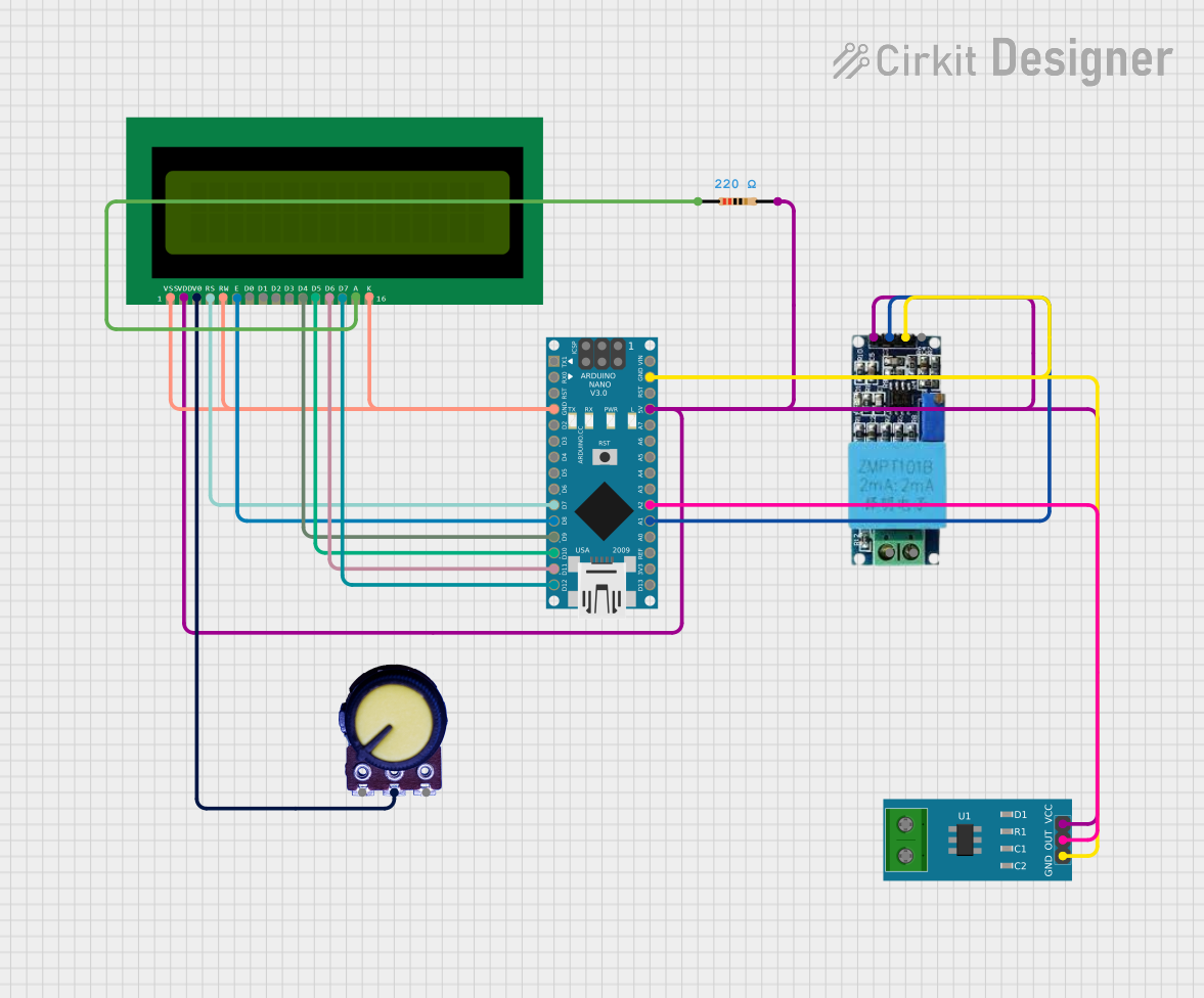
Circuit Documentation
Summary
This circuit is designed to measure voltage and current using a voltage sensor and a current sensor, respectively. The measured values are displayed on a 16x2 LCD screen. The circuit is controlled by an Arduino Nano microcontroller, which reads the sensor values and updates the LCD display accordingly.
Component List
Arduino Nano
- Description: A small, complete, and breadboard-friendly microcontroller board based on the ATmega328P.
- Pins: D1/TX, D0/RX, RESET, GND, D2, D3, D4, D5, D6, D7, D8, D9, D10, D11/MOSI, D12/MISO, VIN, 5V, A7, A6, A5, A4, A3, A2, A1, A0, AREF, 3V3, D13/SCK
Voltage Sensor
- Description: A sensor used to measure voltage.
- Pins: Ground, Phase, Vcc, Out, Gnd
16X2 LCD
- Description: A 16x2 character LCD display.
- Pins: VSS, VDD, V0, RS, RW, E, D1, D0, D2, D3, D4, D6, D5, D7, A, K
Potentiometer
- Description: A variable resistor used to adjust the contrast of the LCD.
- Pins: GND, Output, VCC
Resistor
- Description: A 220 Ohm resistor used to limit current.
- Pins: pin1, pin2
- Properties: Resistance: 220 Ohms
Current Sensor 5A
- Description: A sensor used to measure current up to 5A.
- Pins: 1, 2, GND, OUT, VCC
Wiring Details
Arduino Nano
GND is connected to:
- 16X2 LCD: VSS, K, RW
- Voltage Sensor: Gnd
- Current Sensor 5A: GND
D7 is connected to 16X2 LCD: RS
D8 is connected to 16X2 LCD: E
D9 is connected to 16X2 LCD: D4
D10 is connected to 16X2 LCD: D5
D11/MOSI is connected to 16X2 LCD: D6
D12/MISO is connected to 16X2 LCD: D7
5V is connected to:
- Resistor: pin2
- Voltage Sensor: Vcc
- 16X2 LCD: VDD
- Current Sensor 5A: VCC
A2 is connected to Current Sensor 5A: OUT
A1 is connected to Voltage Sensor: Out
16X2 LCD
V0 is connected to Potentiometer: Output
A is connected to Resistor: pin1
Voltage Sensor
Gnd is connected to Arduino Nano: GND
Vcc is connected to Resistor: pin2
Out is connected to Arduino Nano: A1
Current Sensor 5A
GND is connected to Arduino Nano: GND
VCC is connected to Arduino Nano: 5V
OUT is connected to Arduino Nano: A2
Potentiometer
- Output is connected to 16X2 LCD: V0
Resistor
pin1 is connected to 16X2 LCD: A
pin2 is connected to Arduino Nano: 5V
Code Documentation
/*
 * This Arduino Sketch reads voltage from a voltage sensor connected to A1
 * and current from a current sensor connected to A2. It displays the measured
 * voltage and current on a 16x2 LCD. The LCD is connected to the Arduino Nano
 * as per the specified pin connections.
 */

#include <LiquidCrystal.h>

// Initialize the library with the numbers of the interface pins
LiquidCrystal lcd(7, 8, 9, 10, 11, 12);

// Voltage sensor pin
const int voltageSensorPin = A1;
// Current sensor pin
const int currentSensorPin = A2;

void setup() {
  // Set up the LCD's number of columns and rows:
  lcd.begin(16, 2);
  // Print a message to the LCD.
  lcd.print("Voltage:");
  lcd.setCursor(0, 1);
  lcd.print("Current:");
}

void loop() {
  // Read the input on analog pin A1
  int voltageValue = analogRead(voltageSensorPin);
  // Convert the analog reading (0 - 1023) to a voltage (0 - 5V):
  float voltage = voltageValue * (5.0 / 1023.0);
  // Read the input on analog pin A2
  int currentValue = analogRead(currentSensorPin);
  // Convert the analog reading (0 - 1023) to a current (0 - 5A):
  float current = currentValue * (5.0 / 1023.0);
  // Set the cursor to column 0, line 0
  lcd.setCursor(0, 0);
  // Print the voltage to the LCD
  lcd.print("Voltage: ");
  lcd.print(voltage);
  lcd.print(" V");
  // Set the cursor to column 0, line 1
  lcd.setCursor(0, 1);
  // Print the current to the LCD
  lcd.print("Current: ");
  lcd.print(current);
  lcd.print(" A");
  // Wait for a bit before the next loop
  delay(500);
}
This code initializes the LCD and sets up the pins for the voltage and current sensors. In the loop function, it reads the sensor values, converts them to voltage and current, and displays the values on the LCD.