
Arduino UNO-Based Alarm System with PIR Sensor and RTC Module
View and Edit Project In Cirkit Designer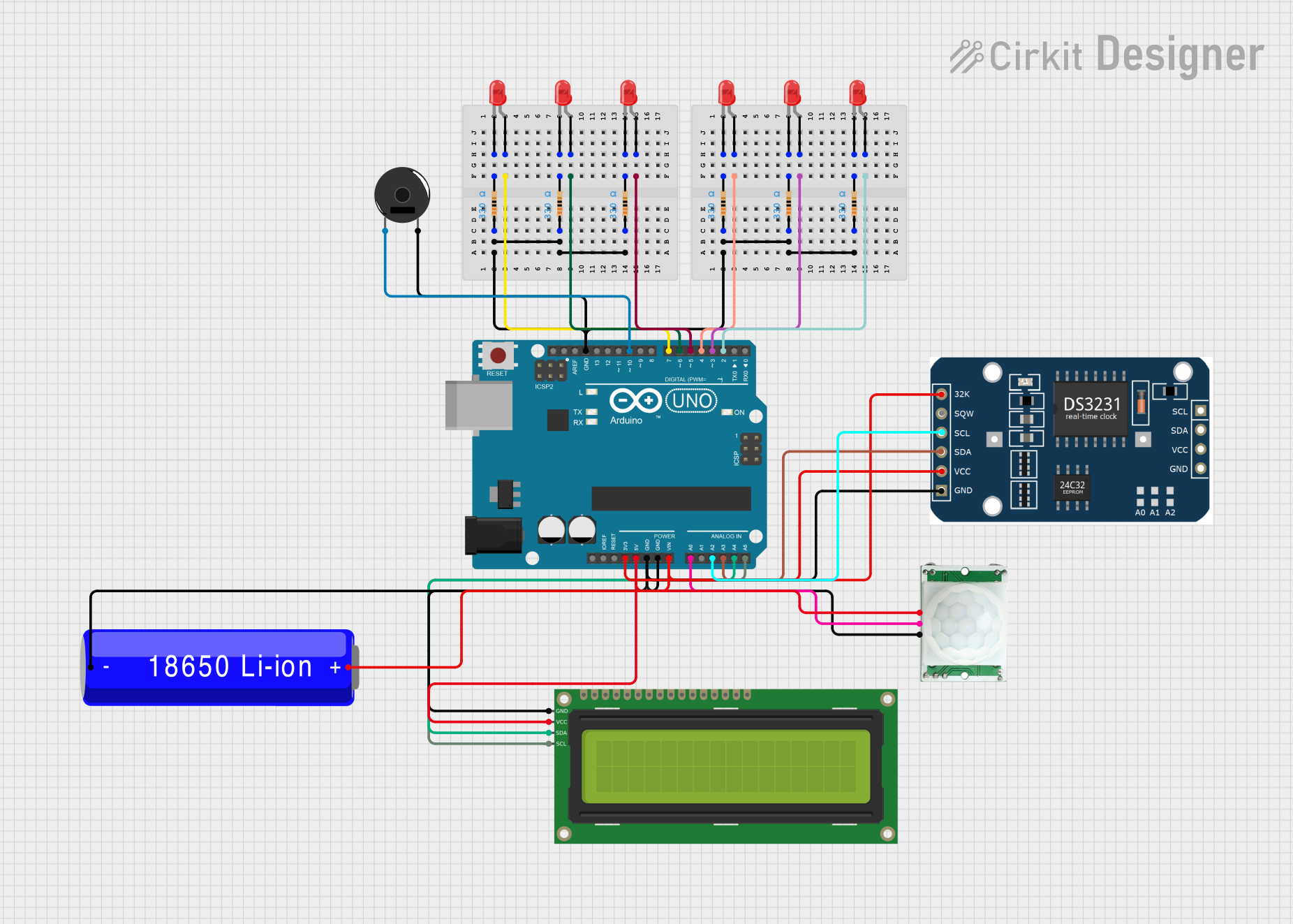
Circuit Documentation
Summary
This circuit is designed to interface with an Arduino UNO microcontroller, a Real-Time Clock (RTC) module, a Passive Infrared (PIR) sensor, a piezo buzzer, and multiple LEDs. The system is programmed to set alarms at 9:00 AM, 12:00 PM, and 9:00 PM. When an alarm triggers, the LEDs blink in a specific order. If the PIR sensor detects motion, the buzzer and LEDs will turn off. The circuit is powered by an 18650 Li-ion battery.
Component List
- Arduino UNO: A microcontroller board based on the ATmega328P. It has digital input/output pins, analog inputs, a USB connection for programming, and power management features.
- PIR/Motion Sensor: A sensor that detects motion based on changes in infrared levels. It has a ground, output, and power connection.
- LED (Red): A two-pin light-emitting diode that emits red light when powered.
- 18650 Li-ion Battery: A rechargeable battery that provides power to the circuit.
- Piezo Buzzer: An electronic device that emits sound when an electrical signal is applied.
- 16x2 I2C LCD: A liquid crystal display that can show 16 characters per line for 2 lines, interfaced via the I2C protocol.
- Resistor (330 Ohms): A passive component used to limit current or divide voltages in the circuit.
- RTC Module: A real-time clock module that keeps track of the current time and date.
Wiring Details
Arduino UNO
- GND: Connected to the ground pins of the PIR/Motion Sensor, 16x2 I2C LCD, RTC Module, and the negative terminal of the 18650 Li-ion Battery.
- 3.3V: Supplies power to the RTC Module.
- 5V: Supplies power to the PIR/Motion Sensor and the 16x2 I2C LCD.
- Vin: Connected to the positive terminal of the 18650 Li-ion Battery.
- A0: Receives the output signal from the PIR/Motion Sensor.
- A2: Connected to the SCL pin of the RTC Module.
- A3: Connected to the SDA pin of the RTC Module.
- A4: Connected to the SDA pin of the 16x2 I2C LCD.
- A5: Connected to the SCL pin of the 16x2 I2C LCD.
- D2 - D7: Connected to the anodes of the LEDs through current-limiting resistors.
- D10: Connected to the pin 1 of the Piezo Buzzer.
PIR/Motion Sensor
- GND: Connected to the ground of the Arduino UNO.
- OUTPUT: Connected to pin A0 of the Arduino UNO.
- VCC: Connected to the 5V output of the Arduino UNO.
LEDs (Red)
- Anode: Connected to digital pins D2 - D7 of the Arduino UNO through current-limiting resistors.
- Cathode: Connected to the ground through current-limiting resistors.
18650 Li-ion Battery
- +: Connected to the Vin pin of the Arduino UNO.
- -: Connected to the GND pin of the Arduino UNO.
Piezo Buzzer
- Pin 1: Connected to digital pin D10 of the Arduino UNO.
- Pin 2: Connected to the ground of the Arduino UNO.
16x2 I2C LCD
- GND: Connected to the ground of the Arduino UNO.
- VCC: Connected to the 5V output of the Arduino UNO.
- SDA: Connected to pin A4 of the Arduino UNO.
- SCL: Connected to pin A5 of the Arduino UNO.
Resistor (330 Ohms)
- Pin1: Connected to the ground of the Arduino UNO.
- Pin2: Connected to the cathodes of the LEDs.
RTC Module
- VCC: Connected to the 3.3V output of the Arduino UNO.
- GND: Connected to the ground of the Arduino UNO.
- SCL: Connected to pin A2 of the Arduino UNO.
- SDA: Connected to pin A3 of the Arduino UNO.
Documented Code
/*
 * This Arduino sketch interfaces with an RTC module, a PIR sensor, a piezo buzzer,
 * and multiple LEDs. The system sets alarms at 9:00 AM, 12:00 PM, and 9:00 PM.
 * When an alarm triggers, LEDs blink in a specific order. If the PIR sensor
 * detects motion, the buzzer and LEDs will turn off.
 */

#include <Wire.h>
#include <RTClib.h>

RTC_DS3231 rtc;

const int buzzerPin = 10;
const int pirPin = A0;
const int ledPins[] = {2, 3, 4, 5, 6, 7};

void setup() {
  Serial.begin(9600);
  if (!rtc.begin()) {
    Serial.println("Couldn't find RTC");
    while (1);
  }
  rtc.adjust(DateTime(F(__DATE__), F(__TIME__)));

  pinMode(buzzerPin, OUTPUT);
  pinMode(pirPin, INPUT);
  for (int i = 0; i < 6; i++) {
    pinMode(ledPins[i], OUTPUT);
  }
}

void loop() {
  DateTime now = rtc.now();
  int pirState = digitalRead(pirPin);

  if (pirState == HIGH) {
    digitalWrite(buzzerPin, LOW);
    for (int i = 0; i < 6; i++) {
      digitalWrite(ledPins[i], LOW);
    }
  } else {
    if ((now.hour() == 9 && now.minute() == 0) ||
        (now.hour() == 12 && now.minute() == 0) ||
        (now.hour() == 21 && now.minute() == 0)) {
      triggerAlarm();
    }
  }
  delay(1000);
}

void triggerAlarm() {
  for (int i = 0; i < 6; i++) {
    digitalWrite(ledPins[i], HIGH);
    delay(500);
    digitalWrite(ledPins[i], LOW);
  }
  tone(buzzerPin, 1000, 1000);
}
This code is responsible for setting up the Arduino UNO to interact with the connected components. It initializes the RTC module, sets up the PIR sensor, buzzer, and LEDs, and contains the main loop that checks for motion and triggers the alarm at the specified times.