Cirkit Designer
Your all-in-one circuit design IDE
Home /
Project Documentation
Arduino UNO and L298N DC Motor Driver Bluetooth Controlled Car
Circuit Documentation
Summary
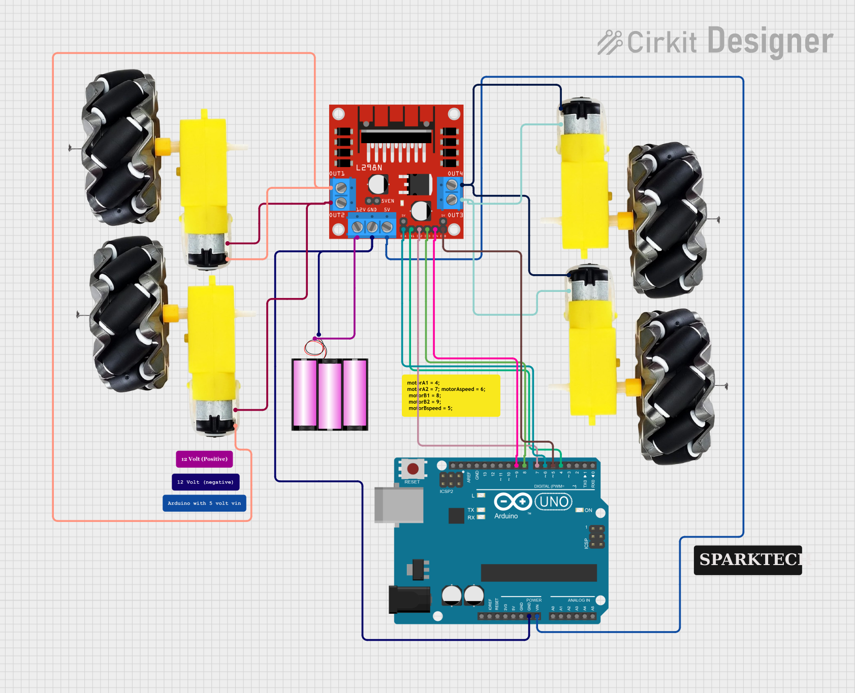
This document provides a detailed overview of a Bluetooth-controlled car circuit. The circuit consists of an Arduino UNO microcontroller, an L298N DC motor driver, a 12V battery, and four motor and wheel assemblies. The Arduino UNO is programmed to control the motors based on commands received via Bluetooth.
Component List
L298N DC Motor Driver
- Description: A dual H-Bridge motor driver that allows control of the speed and direction of two DC motors.
- Pins: OUT1, OUT2, 12V, GND, 5V, OUT3, OUT4, 5V-ENA-JMP-I, 5V-ENA-JMP-O, +5V-J1, +5V-J2, ENA, IN1, IN2, IN3, IN4, ENB
Arduino UNO
- Description: A microcontroller board based on the ATmega328P, used for controlling the motor driver and receiving Bluetooth commands.
- Pins: UNUSED, IOREF, Reset, 3.3V, 5V, GND, Vin, A0, A1, A2, A3, A4, A5, SCL, SDA, AREF, D13, D12, D11, D10, D9, D8, D7, D6, D5, D4, D3, D2, D1, D0
Battery 12V
- Description: A 12V battery used to power the motor driver and the Arduino UNO.
- Pins: +, -
Motor and Wheels
- Description: DC motors with attached wheels, used for driving the car.
- Pins: vcc, GND
Wiring Details
L298N DC Motor Driver
- OUT1 is connected to the vcc pins of two motor and wheel assemblies.
- OUT2 is connected to the GND pins of the same two motor and wheel assemblies.
- 12V is connected to the + pin of the 12V battery.
- GND is connected to the - pin of the 12V battery and the GND pin of the Arduino UNO.
- 5V is connected to the Vin pin of the Arduino UNO.
- OUT3 is connected to the GND pins of the other two motor and wheel assemblies.
- OUT4 is connected to the vcc pins of the same two motor and wheel assemblies.
- ENA is connected to the D6 pin of the Arduino UNO.
- IN1 is connected to the D4 pin of the Arduino UNO.
- IN2 is connected to the D7 pin of the Arduino UNO.
- IN3 is connected to the D8 pin of the Arduino UNO.
- IN4 is connected to the D9 pin of the Arduino UNO.
- ENB is connected to the D5 pin of the Arduino UNO.
Arduino UNO
- GND is connected to the - pin of the 12V battery and the GND pin of the L298N DC motor driver.
- Vin is connected to the 5V pin of the L298N DC motor driver.
- D6 is connected to the ENA pin of the L298N DC motor driver.
- D4 is connected to the IN1 pin of the L298N DC motor driver.
- D7 is connected to the IN2 pin of the L298N DC motor driver.
- D8 is connected to the IN3 pin of the L298N DC motor driver.
- D9 is connected to the IN4 pin of the L298N DC motor driver.
- D5 is connected to the ENB pin of the L298N DC motor driver.
Battery 12V
- + is connected to the 12V pin of the L298N DC motor driver.
- - is connected to the GND pin of the Arduino UNO and the GND pin of the L298N DC motor driver.
Motor and Wheels
- vcc of the first two motor and wheel assemblies is connected to the OUT1 pin of the L298N DC motor driver.
- GND of the first two motor and wheel assemblies is connected to the OUT2 pin of the L298N DC motor driver.
- vcc of the other two motor and wheel assemblies is connected to the OUT4 pin of the L298N DC motor driver.
- GND of the other two motor and wheel assemblies is connected to the OUT3 pin of the L298N DC motor driver.
Code Documentation
Arduino UNO Code
// Arduino Bluetooth Controlled Car
// Before uploading the code you have to install the necessary library
// Note - Disconnect the Bluetooth Module before hitting the upload button otherwise you'll get a compilation error message.
// AFMotor Library https://learn.adafruit.com/adafruit-motor-shield/library-install
// After downloading the library open Arduino IDE >> go to sketch >> Include Library >> ADD. ZIP Library >> Select the downloaded
// ZIP File >> Open it >> Done
// Now You Can Upload the Code without any problem but make sure the bt module isn't connected with Arduino while uploading code

#include <AFMotor.h>

// initial motors pin
AF_DCMotor motor1(1, MOTOR12_1KHZ);
AF_DCMotor motor2(2, MOTOR12_1KHZ);
AF_DCMotor motor3(3, MOTOR34_1KHZ);
AF_DCMotor motor4(4, MOTOR34_1KHZ);

char command;

void setup()
{
  Serial.begin(9600);  // Set the baud rate to your Bluetooth module.
}

void loop(){
  if(Serial.available() > 0){
    command = Serial.read();
    Stop(); // initialize with motors stopped
    // Change pin mode only if new command is different from previous.
    // Serial.println(command);
    switch(command){
    case 'F':
      forward();
      break;
    case 'B':
       back();
      break;
    case 'L':
      left();
      break;
    case 'R':
      right();
      break;
    }
  }
}

void forward()
{
  motor1.setSpeed(255); // Define maximum velocity
  motor1.run(FORWARD); // rotate the motor clockwise
  motor2.setSpeed(255); // Define maximum velocity
  motor2.run(FORWARD); // rotate the motor clockwise
  motor3.setSpeed(255); // Define maximum velocity
  motor3.run(FORWARD); // rotate the motor clockwise
  motor4.setSpeed(255); // Define maximum velocity
  motor4.run(FORWARD); // rotate the motor clockwise
}

void back()
{
  motor1.setSpeed(255); // Define maximum velocity
  motor1.run(BACKWARD); // rotate the motor anti-clockwise
  motor2.setSpeed(255); // Define maximum velocity
  motor2.run(BACKWARD); // rotate the motor anti-clockwise
  motor3.setSpeed(255); // Define maximum velocity
  motor3.run(BACKWARD); // rotate the motor anti-clockwise
  motor4.setSpeed(255); // Define maximum velocity
  motor4.run(BACKWARD); // rotate the motor anti-clockwise
}

void left()
{
  motor1.setSpeed(255); // Define maximum velocity
  motor1.run(BACKWARD); // rotate the motor anti-clockwise
  motor2.setSpeed(255); // Define maximum velocity
  motor2.run(BACKWARD); // rotate the motor anti-clockwise
  motor3.setSpeed(255); // Define maximum velocity
  motor3.run(FORWARD);  // rotate the motor clockwise
  motor4.setSpeed(255); // Define maximum velocity
  motor4.run(FORWARD);  // rotate the motor clockwise
}

void right()
{
  motor1.setSpeed(255); // Define maximum velocity
  motor1.run(FORWARD); // rotate the motor clockwise
  motor2.setSpeed(255); // Define maximum velocity
  motor2.run(FORWARD); // rotate the motor clockwise
  motor3.setSpeed(255); // Define maximum velocity
  motor3.run(BACKWARD); // rotate the motor anti-clockwise
  motor4.setSpeed(255); // Define maximum velocity
  motor4.run(BACKWARD); // rotate the motor anti-clockwise
}

void Stop()
{
  motor1.setSpeed(0); // Define minimum velocity
  motor1.run(RELEASE); // stop the motor when release the button
  motor2.setSpeed(0); // Define minimum velocity
  motor2.run(RELEASE); // rotate the motor clockwise
  motor3.setSpeed(0); // Define minimum velocity
  motor3.run(RELEASE); // stop the motor when release the button
  motor4.setSpeed(0); // Define minimum velocity
  motor4.run(RELEASE); // stop the motor when release the button
}
This code initializes the motors and sets up the serial communication for