
Circuit Documentation
Summary
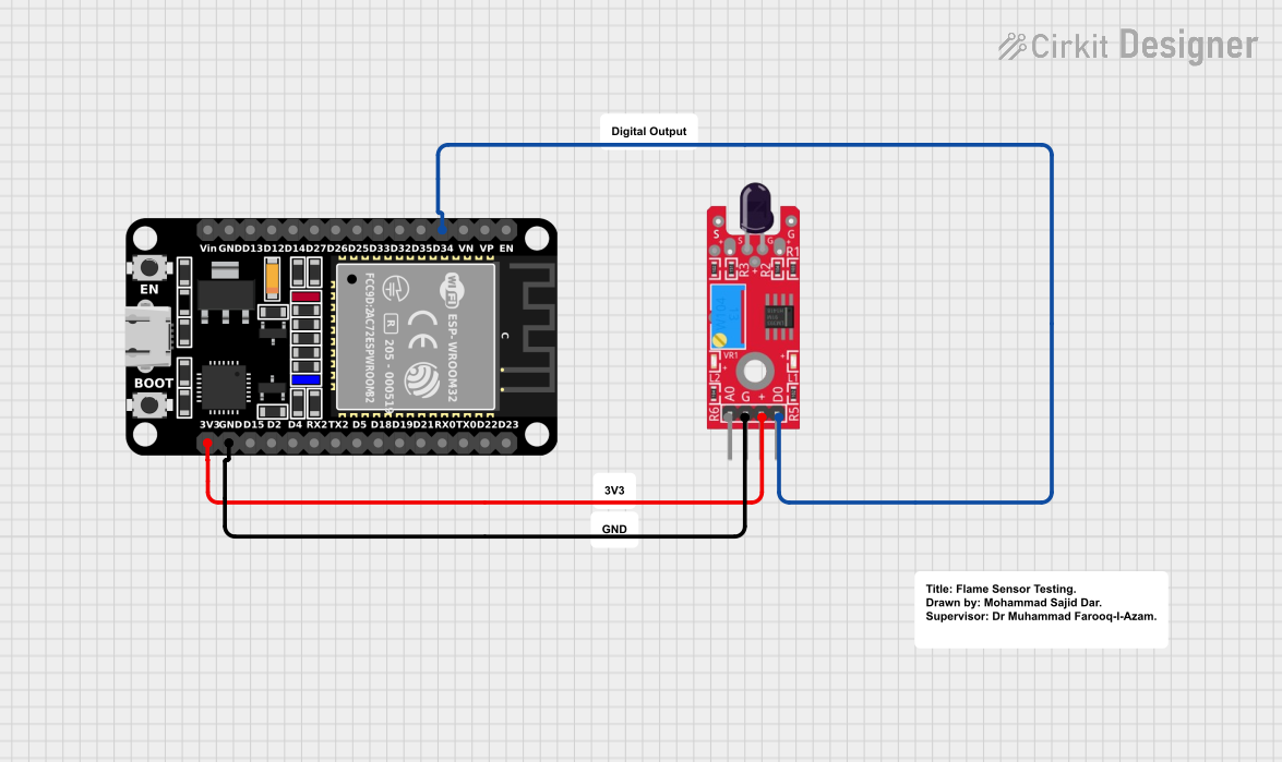
This document provides a detailed overview of a circuit that includes an ESP32 microcontroller and a KY-026 Flame Sensor. The ESP32 is used to read the digital output from the flame sensor, which detects the presence of a flame. The circuit is powered by the 3.3V supply from the ESP32.
Component List
KY-026 Flame Sensor
- Description: A sensor module used to detect flame or fire.
- Pins: AO, GND, VCC, DO
- Purpose in Circuit: Detects the presence of a flame and sends a digital signal to the ESP32.
ESP32 (30 pin)
- Description: A low-cost, low-power system on a chip microcontroller with integrated Wi-Fi and dual-mode Bluetooth.
- Pins: EN, VP, VN, D34, D35, D32, D33, D25, D26, D27, D14, D12, D13, GND, Vin, D23, D22, TX0, RX0, D21, D19, D18, D5, TX2, RX2, D4, D2, D15, 3V3
- Purpose in Circuit: Reads the digital output from the flame sensor and can be programmed to take appropriate actions based on the sensor input.
Comment
- Description: Placeholder for comments or notes in the circuit design.
- Pins: None
- Purpose in Circuit: Not applicable.
Wiring Details
KY-026 Flame Sensor
- GND is connected to GND of the ESP32.
- VCC is connected to 3V3 of the ESP32.
- DO is connected to D34 of the ESP32.
ESP32 (30 pin)
- GND is connected to GND of the KY-026 Flame Sensor.
- 3V3 is connected to VCC of the KY-026 Flame Sensor.
- D34 is connected to DO of the KY-026 Flame Sensor.
Code
There is no code provided for this circuit.
This document provides a comprehensive overview of the circuit, including the components used, their connections, and their roles within the circuit.