Cirkit Designer
Your all-in-one circuit design IDE
Home /
Project Documentation
Arduino-Controlled Robotics Platform with Dual DC Motors and Servo Steering
Circuit Documentation
Summary of the Circuit
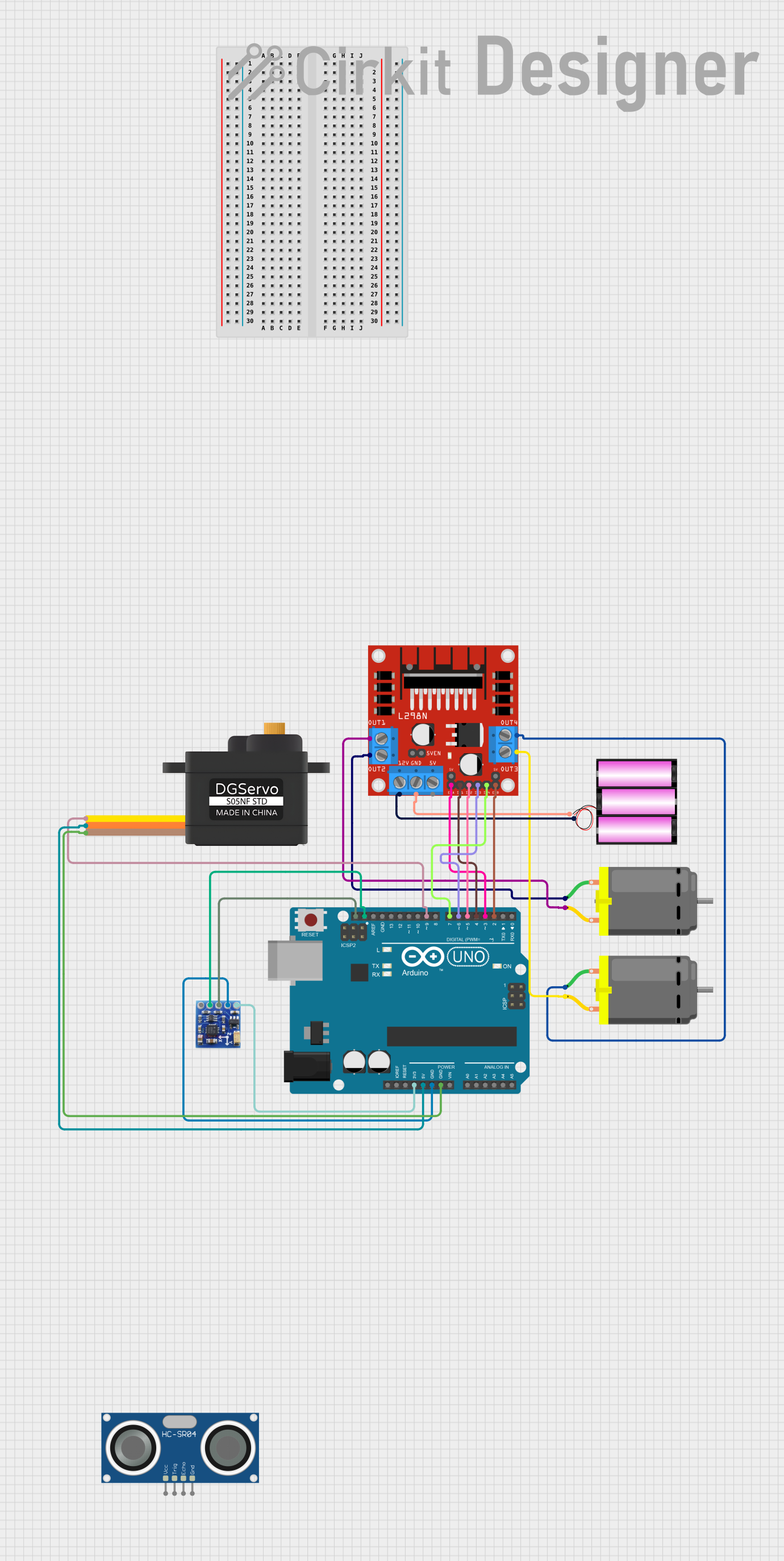
This circuit is designed to control two DC motors using an L298N DC motor driver, which is interfaced with an Arduino UNO microcontroller. The circuit also includes a servomotor and an HC-SR04 ultrasonic sensor for distance measurement, as well as a QMC5883L magnetometer for detecting magnetic fields. The entire system is powered by a 12V battery. The Arduino UNO manages the logic and sensor data processing, while the L298N driver module controls the motor speeds and directions.
Component List
Arduino UNO
- Microcontroller board based on the ATmega328P
- Used for controlling the logic of the circuit and processing sensor data
L298N DC Motor Driver
- Dual H-Bridge motor driver
- Used for driving two DC motors with direction and speed control
Battery 12V
- Power source for the motor driver and motors
DC Motor (2x)
- Electric motors that convert electrical energy into mechanical motion
- Controlled by the L298N motor driver
Servomotor S05NF
- Rotary actuator that allows for precise control of angular position
- Powered and controlled by the Arduino UNO
HC-SR04 Ultrasonic Sensor
- Sensor that uses ultrasonic waves to measure distance
- Interfaced with the Arduino UNO for distance measurement
QMC5883L Magnetometer
- Sensor that measures the strength and direction of magnetic fields
- Connected to the Arduino UNO via I2C communication
Wiring Details
Arduino UNO
3.3Vconnected to QMC5883L Magnetometer VCC5Vconnected to Servomotor S05NF VCCGNDconnected to QMC5883L Magnetometer GND and Servomotor S05NF GNDSCLconnected to QMC5883L Magnetometer SCLSDAconnected to QMC5883L Magnetometer SDAD9connected to Servomotor S05NF SIGD7connected to L298N DC motor driver IN4D6connected to L298N DC motor driver IN3D5connected to L298N DC motor driver IN2D4connected to L298N DC motor driver IN1D3connected to L298N DC motor driver ENAD2connected to L298N DC motor driver ENB
L298N DC Motor Driver
12Vconnected to Battery 12V positive terminalGNDconnected to Battery 12V negative terminalOUT1connected to DC Motor 1 pin 2OUT2connected to DC Motor 1 pin 1OUT3connected to DC Motor 2 pin 2OUT4connected to DC Motor 2 pin 1
Battery 12V
+connected to L298N DC motor driver 12V-connected to L298N DC motor driver GND
DC Motor 1 & 2
pin 1connected to L298N DC motor driver OUT2 (Motor 1) and OUT4 (Motor 2)pin 2connected to L298N DC motor driver OUT1 (Motor 1) and OUT3 (Motor 2)
Servomotor S05NF
SIGconnected to Arduino UNO D9VCCconnected to Arduino UNO 5VGNDconnected to Arduino UNO GND
QMC5883L Magnetometer
VCCconnected to Arduino UNO 3.3VGNDconnected to Arduino UNO GNDSCLconnected to Arduino UNO SCLSDAconnected to Arduino UNO SDA
Documented Code
Arduino UNO Code (sketch.ino)
void setup() {
  // put your setup code here, to run once:

}

void loop() {
  // put your main code here, to run repeatedly:

}
Note: The provided code is a template and does not contain any functional code. It needs to be populated with the logic for controlling the motors, reading sensor data, and any other required functionality.