Cirkit Designer
Your all-in-one circuit design IDE
Home /
Project Documentation
Arduino UNO and HC-05 Bluetooth Controlled RC Car with L298N Motor Driver
Circuit Documentation
Summary
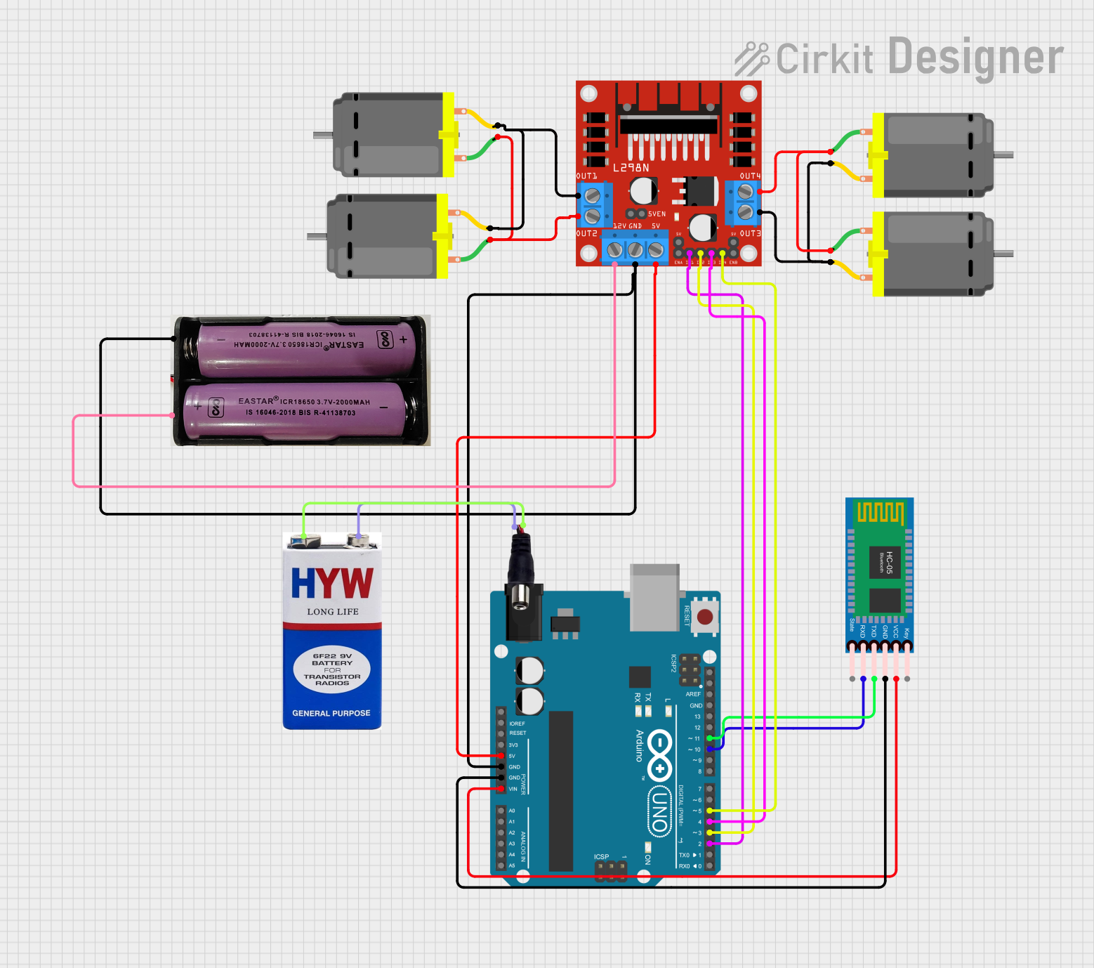
This document provides a detailed overview of a Bluetooth-controlled RC car circuit. The circuit uses an Arduino UNO microcontroller, an HC-05 Bluetooth module, an L298N motor driver, and four DC motors. The car can be controlled via a Bluetooth connection from a smartphone or other Bluetooth-enabled device.
Component List
HC-05 Bluetooth Module
- Description: A Bluetooth module used for wireless communication.
- Pins: Key, VCC, GND, TXD, RXD, State
L298N DC Motor Driver
- Description: A dual H-bridge motor driver that allows control of two DC motors.
- Pins: OUT1, OUT2, 12V, GND, 5V, OUT3, OUT4, 5V-ENA-JMP-I, 5V-ENA-JMP-O, +5V-J1, +5V-J2, ENA, IN1, IN2, IN3, IN4, ENB
Arduino UNO
- Description: A microcontroller board based on the ATmega328P.
- Pins: UNUSED, IOREF, Reset, 3.3V, 5V, GND, Vin, A0, A1, A2, A3, A4, A5, SCL, SDA, AREF, D13, D12, D11, D10, D9, D8, D7, D6, D5, D4, D3, D2, D1, D0
DC Motor (4 units)
- Description: Standard DC motors used for driving the wheels of the RC car.
- Pins: pin 1, pin 2
9V Battery
- Description: A 9V battery used to power the circuit.
- Pins: +, -
7.4V Battery
- Description: A 7.4V battery used to power the motor driver.
- Pins: +, -
Power Jack
- Description: A power jack used to connect the 9V battery to the circuit.
- Pins: POSITIF, NEGATIF
Wiring Details
HC-05 Bluetooth Module
- VCC connected to Vin of Arduino UNO
- GND connected to GND of Arduino UNO
- TXD connected to D11 of Arduino UNO
- RXD connected to D10 of Arduino UNO
L298N DC Motor Driver
- OUT1 connected to pin 2 of DC Motor 1 and pin 2 of DC Motor 2
- OUT2 connected to pin 1 of DC Motor 1 and pin 1 of DC Motor 2
- OUT3 connected to pin 2 of DC Motor 3 and pin 2 of DC Motor 4
- OUT4 connected to pin 1 of DC Motor 3 and pin 1 of DC Motor 4
- 12V connected to + of 7.4V Battery
- GND connected to - of 7.4V Battery and GND of Arduino UNO
- 5V connected to 5V of Arduino UNO
- IN1 connected to D2 of Arduino UNO
- IN2 connected to D3 of Arduino UNO
- IN3 connected to D4 of Arduino UNO
- IN4 connected to D5 of Arduino UNO
Arduino UNO
- Vin connected to VCC of HC-05 Bluetooth Module
- GND connected to GND of HC-05 Bluetooth Module and GND of L298N DC Motor Driver
- D11 connected to TXD of HC-05 Bluetooth Module
- D10 connected to RXD of HC-05 Bluetooth Module
- D2 connected to IN1 of L298N DC Motor Driver
- D3 connected to IN2 of L298N DC Motor Driver
- D4 connected to IN3 of L298N DC Motor Driver
- D5 connected to IN4 of L298N DC Motor Driver
- 5V connected to 5V of L298N DC Motor Driver
DC Motors
DC Motor 1
- pin 1 connected to OUT2 of L298N DC Motor Driver
- pin 2 connected to OUT1 of L298N DC Motor Driver
DC Motor 2
- pin 1 connected to OUT2 of L298N DC Motor Driver
- pin 2 connected to OUT1 of L298N DC Motor Driver
DC Motor 3
- pin 1 connected to OUT4 of L298N DC Motor Driver
- pin 2 connected to OUT3 of L298N DC Motor Driver
DC Motor 4
- pin 1 connected to OUT4 of L298N DC Motor Driver
- pin 2 connected to OUT3 of L298N DC Motor Driver
9V Battery
- + connected to POSITIF of Power Jack
- - connected to NEGATIF of Power Jack
7.4V Battery
- + connected to 12V of L298N DC Motor Driver
- - connected to GND of L298N DC Motor Driver
Power Jack
- POSITIF connected to + of 9V Battery
- NEGATIF connected to - of 9V Battery
Code Documentation
/*
 * Arduino-based Bluetooth Controlled RC Car
 * This code allows an Arduino UNO to control an RC car using an HC-05 Bluetooth
 * module and an L298N motor driver. The car can be controlled via a Bluetooth
 * connection from a smartphone or other Bluetooth-enabled device.
 */

#include <SoftwareSerial.h>

// Bluetooth module pins
const int bluetoothTx = 11;
const int bluetoothRx = 10;

// Motor driver pins
const int motorIn1 = 2;
const int motorIn2 = 3;
const int motorIn3 = 4;
const int motorIn4 = 5;

// Create a software serial port for the Bluetooth module
SoftwareSerial bluetooth(bluetoothTx, bluetoothRx);

void setup() {
  // Initialize serial communication
  Serial.begin(9600);
  bluetooth.begin(9600);

  // Initialize motor driver pins as outputs
  pinMode(motorIn1, OUTPUT);
  pinMode(motorIn2, OUTPUT);
  pinMode(motorIn3, OUTPUT);
  pinMode(motorIn4, OUTPUT);
}

void loop() {
  // Check if data is available from the Bluetooth module
  if (bluetooth.available()) {
    char command = bluetooth.read();
    Serial.println(command);

    // Control the motors based on the received command
    switch (command) {
      case 'F': // Move forward
        digitalWrite(motorIn1, HIGH);
        digitalWrite(motorIn2, LOW);
        digitalWrite(motorIn3, HIGH);
        digitalWrite(motorIn4, LOW);
        break;
      case 'B': // Move backward
        digitalWrite(motorIn1, LOW);
        digitalWrite(motorIn2, HIGH);
        digitalWrite(motorIn3, LOW);
        digitalWrite(motorIn4, HIGH);
        break;
      case 'L': // Turn left
        digitalWrite(motorIn1, LOW);
        digitalWrite(motorIn2, HIGH);
        digitalWrite(motorIn3, HIGH);
        digitalWrite(motorIn4, LOW);
        break;
      case 'R': // Turn right
        digitalWrite(motorIn1, HIGH);
        digitalWrite(motorIn2, LOW);
        digitalWrite(motorIn3, LOW);
        digitalWrite(motorIn4, HIGH);
        break;
      case 'S': // Stop
        digitalWrite(motorIn1, LOW);
        digitalWrite(motorIn2, LOW);
        digitalWrite(motorIn3, LOW);
        digitalWrite(motorIn4, LOW);
        break;
    }
  }
}
This code initializes the Bluetooth module and motor driver pins, then continuously checks for commands received via Bluetooth to control the motors accordingly.