
Arduino Nano-Based Battery-Powered Line Following Robot with Reflectance Sensor and Motor Driver
View and Edit Project In Cirkit Designer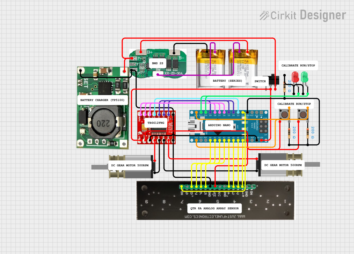
Circuit Documentation
Summary
This document provides a detailed overview of a circuit that includes various components such as DC motors, pushbuttons, a toggle switch, a LiPo battery, a reflectance sensor array, LEDs, resistors, an Arduino Nano, a motor driver, a battery management system (BMS), and a TP5100 charger. The circuit is designed to control motors and LEDs using an Arduino Nano, with inputs from pushbuttons and a reflectance sensor array.
Component List
DC Mini Metal Gear Motor
- Pins: IN1, IN2
- Description: A small DC motor with metal gears for increased torque.
- Purpose: Used to drive mechanical components.
Pushbutton
- Pins: Pin 1 (in), Pin 2 (in), Pin 3 (out), Pin 4 (out)
- Description: A simple pushbutton switch.
- Purpose: Used to provide user input to the circuit.
Toggle Switch
- Pins: L1, COM, L2
- Description: A switch that toggles between two states.
- Purpose: Used to control the power supply to the circuit.
3.7v LiPo
- Pins: +Ve, GND
- Description: A 3.7V Lithium Polymer battery.
- Purpose: Provides power to the circuit.
Reflectance Sensor Array 9 pin
- Pins: ON, GND, 1, 2, 3, 4, VCC, 5, 6, 7, 8, 9
- Description: An array of sensors used to detect reflectance.
- Purpose: Used for line-following or object detection.
LED: Two Pin (red)
- Pins: cathode, anode
- Description: A red LED.
- Purpose: Used for visual indication.
LED: Two Pin (green)
- Pins: cathode, anode
- Description: A green LED.
- Purpose: Used for visual indication.
Resistor
- Pins: pin1, pin2
- Description: A resistor with a resistance of 200 Ohms.
- Purpose: Used to limit current in the circuit.
Arduino Nano
- Pins: D1/TX, D0/RX, RESET, GND, D2, D3, D4, D5, D6, D7, D8, D9, D10, D11/MOSI, D12/MISO, VIN, 5V, A7, A6, A5, A4, A3, A2, A1, A0, AREF, 3V3, D13/SCK
- Description: A small, complete, and breadboard-friendly microcontroller board.
- Purpose: Used to control the circuit.
TB6612FNG Motor Driver
- Pins: GND, B01, B02, A02, A01, VCC, VM, PWMB, BI2, BI1, STBY, AI1, AI2, PWMA
- Description: A motor driver IC.
- Purpose: Used to drive the DC motors.
2S 30A BMS
- Pins: B+, B-, BM, P-, T, P+
- Description: A battery management system for 2S LiPo batteries.
- Purpose: Used to manage and protect the LiPo batteries.
TP5100
- Pins: B-, B+, IN-, IN+
- Description: A charger module for LiPo batteries.
- Purpose: Used to charge the LiPo batteries.
Wiring Details
DC Mini Metal Gear Motor
Motor 1:
- IN1 connected to A02 of TB6612FNG Motor Driver
- IN2 connected to A01 of TB6612FNG Motor Driver
Motor 2:
- IN1 connected to B01 of TB6612FNG Motor Driver
- IN2 connected to B02 of TB6612FNG Motor Driver
Pushbutton
Pushbutton 1:
- Pin 3 (out) connected to D12/MISO of Arduino Nano
- Pin 2 (in) connected to 5V of Arduino Nano
Pushbutton 2:
- Pin 3 (out) connected to D13/SCK of Arduino Nano
- Pin 2 (in) connected to 5V of Arduino Nano
Toggle Switch
- COM connected to VM of TB6612FNG Motor Driver
- L2 connected to P+ of 2S 30A BMS
3.7v LiPo
Battery 1:
- +Ve connected to B+ of 2S 30A BMS
- GND connected to BM of 2S 30A BMS
Battery 2:
- +Ve connected to BM of 2S 30A BMS
- GND connected to B- of 2S 30A BMS
Reflectance Sensor Array 9 pin
- ON connected to D2 of Arduino Nano
- GND connected to GND of Arduino Nano
- VCC connected to 5V of Arduino Nano
- Pin 1 connected to A7 of Arduino Nano
- Pin 2 connected to A6 of Arduino Nano
- Pin 3 connected to A5 of Arduino Nano
- Pin 4 connected to A4 of Arduino Nano
- Pin 5 connected to A3 of Arduino Nano
- Pin 6 connected to A2 of Arduino Nano
- Pin 7 connected to A1 of Arduino Nano
- Pin 8 connected to A0 of Arduino Nano
LED: Two Pin (red)
- Anode connected to D11/MOSI of Arduino Nano
- Cathode connected to cathode of green LED
LED: Two Pin (green)
- Anode connected to D10 of Arduino Nano
- Cathode connected to cathode of red LED
Resistor
Resistor 1:
- Pin 2 connected to GND of Arduino Nano
Resistor 2:
- Pin 2 connected to GND of Arduino Nano
Resistor 3:
- Pin 2 connected to GND of Arduino Nano
- Pin 1 connected to cathode of red LED
Arduino Nano
- D2 connected to ON of Reflectance Sensor Array
- D3 connected to STBY of TB6612FNG Motor Driver
- D4 connected to BI2 of TB6612FNG Motor Driver
- D5 connected to BI1 of TB6612FNG Motor Driver
- D6 connected to PWMA of TB6612FNG Motor Driver
- D7 connected to AI1 of TB6612FNG Motor Driver
- D8 connected to AI2 of TB6612FNG Motor Driver
- D9 connected to PWMB of TB6612FNG Motor Driver
- D10 connected to anode of green LED
- D11/MOSI connected to anode of red LED
- D12/MISO connected to Pin 3 (out) of Pushbutton 1
- VIN connected to COM of Toggle Switch
- GND connected to GND of TB6612FNG Motor Driver
- 5V connected to VCC of TB6612FNG Motor Driver
TB6612FNG Motor Driver
- STBY connected to D3 of Arduino Nano
- BI2 connected to D4 of Arduino Nano
- BI1 connected to D5 of Arduino Nano
- PWMA connected to D6 of Arduino Nano
- AI1 connected to D7 of Arduino Nano
- AI2 connected to D8 of Arduino Nano
- PWMB connected to D9 of Arduino Nano
- VM connected to COM of Toggle Switch
- VCC connected to 5V of Arduino Nano
- GND connected to GND of Arduino Nano
2S 30A BMS
- P- connected to GND of TB6612FNG Motor Driver
- P+ connected to L2 of Toggle Switch
- B+ connected to +Ve of 3.7v LiPo Battery 1
- BM connected to +Ve of 3.7v LiPo Battery 2
- B- connected to GND of 3.7v LiPo Battery 2
TP5100
- B+ connected to P+ of 2S 30A BMS
- B- connected to P- of 2S 30A BMS
Documented Code
Arduino Nano Code
void setup() {
  // put your setup code here, to run once:

}

void loop() {
  // put your main code here, to run repeatedly:

}
This concludes the documentation for the circuit. Each component and its connections have been detailed, along with the code used for the Arduino Nano.