
12V Geared Motor Control with Diode Protection and LED Indicator
View and Edit Project In Cirkit Designer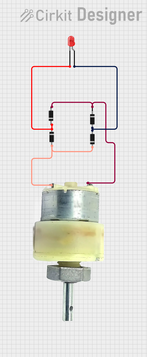
Circuit Documentation
Summary
This document provides a detailed description of a circuit consisting of diodes, an LED, and a 12V geared motor. The circuit includes the interconnections between these components and their respective roles. No microcontroller code is included in this circuit.
Component List
Diode
- Description: A semiconductor device that allows current to flow in one direction only.
- Pins: Cathode, Anode
LED: Two Pin (red)
- Description: A light-emitting diode that emits red light when current flows through it.
- Pins: Cathode, Anode
12V Geared Motor
- Description: A motor that operates on 12V and includes a gear mechanism to reduce speed and increase torque.
- Pins: Terminal 1, Terminal 2
Wiring Details
Diode 1
- Cathode: Connected to Terminal 1 of the 12V Geared Motor
- Anode: Connected to the Anode of Diode 4
Diode 2
- Anode: Connected to the Anode of Diode 1 and the Anode of the LED
- Cathode: Connected to Terminal 2 of the 12V Geared Motor
Diode 3
- Anode: Connected to the Cathode of Diode 2
- Cathode: Connected to the Cathode of Diode 4 and the Cathode of the LED
Diode 4
- Anode: Connected to the Cathode of Diode 1
- Cathode: Connected to the Cathode of Diode 3 and the Cathode of the LED
LED: Two Pin (red)
- Anode: Connected to the Anode of Diode 2
- Cathode: Connected to the Cathode of Diode 3 and the Cathode of Diode 4
12V Geared Motor
- Terminal 1: Connected to the Cathode of Diode 1
- Terminal 2: Connected to the Cathode of Diode 2
Code
No microcontroller code is included in this circuit.
This document provides a comprehensive overview of the circuit, including the components used and their interconnections. The detailed wiring information ensures accurate assembly and troubleshooting of the circuit.