
Arduino UNO-Based Smart Home Security System with PIR Motion Sensor and Smoke Detection
View and Edit Project In Cirkit Designer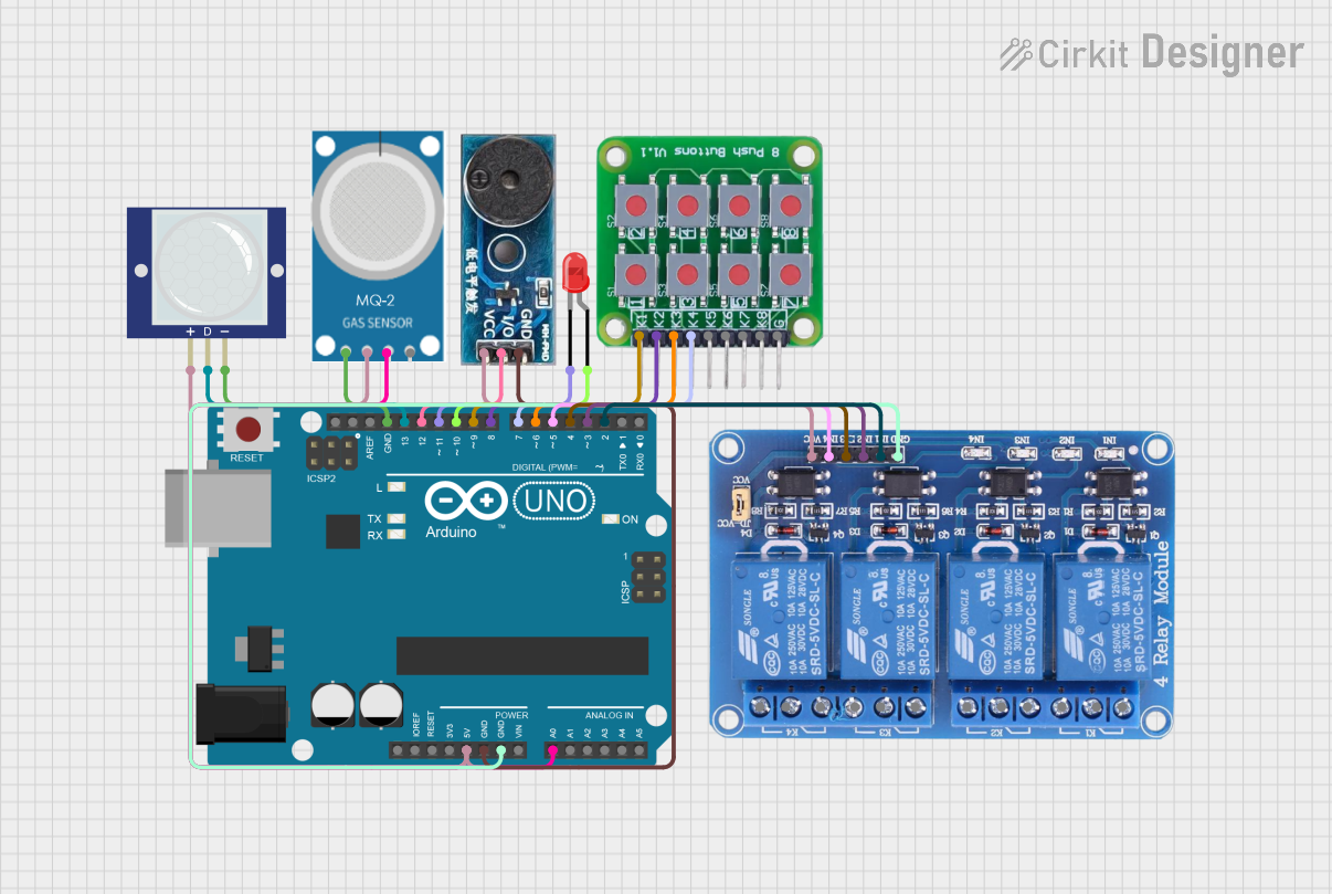
Circuit Documentation
Summary
This circuit is designed to integrate various sensors and actuators with an Arduino UNO microcontroller. The components include a PIR motion sensor, an MQ-2 gas sensor, a red LED, a buzzer module, a 4-channel relay, and an 8 push button board. The Arduino UNO serves as the central controller, processing inputs from the sensors and buttons and controlling the actuators accordingly.
Component List
PIR Motion Sensor (Wokwi Compatible)
- Pins: VCC, OUT, GND
- Description: Detects motion and outputs a high signal when motion is detected.
LED: Two Pin (red)
- Pins: Cathode, Anode
- Description: A red LED used for visual indication.
MQ-2
- Pins: GND, VCC, ANALOG, Digital
- Description: A gas sensor that detects smoke and other gases.
Buzzer Module
- Pins: GND, Vcc, I/O
- Description: Emits sound when activated.
Relay 4 Channel 5v
- Pins: GND, IN1, IN2, IN3, IN4, VCC, COM1, COM2, COM3, COM4, NO1, NO2, NO3, NO4, NC1, NC2, NC3, NC4
- Description: Controls high voltage devices with low voltage signals.
8 Push Button Board PCB
- Pins: K1, K2, K3, K4, K5, K6, K7, K8, GROUND
- Description: A board with 8 push buttons for user input.
Arduino UNO
- Pins: UNUSED, IOREF, Reset, 3.3V, 5V, GND, Vin, A0, A1, A2, A3, A4, A5, SCL, SDA, AREF, D13, D12, D11, D10, D9, D8, D7, D6, D5, D4, D3, D2, D1, D0
- Description: A microcontroller board based on the ATmega328P.
Wiring Details
PIR Motion Sensor (Wokwi Compatible)
- VCC connected to Arduino UNO 5V
- OUT connected to Arduino UNO D13
- GND connected to Arduino UNO GND
LED: Two Pin (red)
- Cathode connected to Arduino UNO D11
- Anode connected to Arduino UNO D10
MQ-2
- GND connected to Arduino UNO GND
- VCC connected to Arduino UNO 5V
- ANALOG connected to Arduino UNO A0
Buzzer Module
- GND connected to Arduino UNO GND
- Vcc connected to Arduino UNO 5V
- I/O connected to Arduino UNO D12
Relay 4 Channel 5v
- GND connected to Arduino UNO GND
- VCC connected to Arduino UNO 5V
- IN1 connected to Arduino UNO D2
- IN2 connected to Arduino UNO D3
- IN3 connected to Arduino UNO D4
- IN4 connected to Arduino UNO D5
8 Push Button Board PCB
- K1 connected to Arduino UNO D9
- K2 connected to Arduino UNO D8
- K3 connected to Arduino UNO D6
- K4 connected to Arduino UNO D7
Documented Code
void setup() {
  // Set up ports
  DDRB = 0xFF; // Set PORTB as output
  DDRD = 0xFF; // Set PORTD as output
  DDRC &= ~(1 << PINC0); // Set A0 as input for smoke sensor
  DDRD &= ~(1 << PIND9) & ~(1 << PIND8) & ~(1 << PIND6) & ~(1 << PIND7); // Set buttons as input
}

void loop() {
  // Check PIR sensor
  if (PIND & (1 << PINB5)) {
    PORTB |= (1 << PINB2); // Turn on LED
  } else {
    PORTB &= ~(1 << PINB2); // Turn off LED
  }

  // Check smoke sensor
  if (ADC(PINC0) > 300) { // Threshold for smoke detection
    PORTB |= (1 << BUZZER_PIN); // Turn on buzzer
    delay(300000); // Wait for 5 minutes
    PORTB &= ~(1 << BUZZER_PIN); // Turn off buzzer
  }

  // Check buttons and control relays
  if (PIND & (1 << PINB1)) {
    PORTD |= (1 << PIND2); // Turn on relay 1
  } else {
    PORTD &= ~(1 << PIND2); // Turn off relay 1
  }

  if (PIND & (1 << PINB0)) {
    PORTD |= (1 << PIND3); // Turn on relay 2
  } else {
    PORTD &= ~(1 << PIND3); // Turn off relay 2
  }

  if (PIND & (1 << PIND6)) {
    PORTD |= (1 << PIND4); // Turn on relay 3
  } else {
    PORTD &= ~(1 << PIND4); // Turn off relay 3
  }

  if (PIND & (1 << PIND7)) {
    PORTD |= (1 << PIND5); // Turn on relay 4
  } else {
    PORTD &= ~(1 << PIND5); // Turn off relay 4
  }
}

void ADC(double smoke) {
  ADMUX = 0x22;
  ADCSRA = 0x86;
  while (1) {
    ADCSRA |= (1 << ADSC);
    while ((ADCSRA & 0x10) == 0);
    return ADCH;
  }
}
This code sets up the Arduino UNO to read inputs from the PIR motion sensor, MQ-2 gas sensor, and push buttons, and control the LED, buzzer, and relays accordingly. The setup function configures the input and output ports, while the loop function continuously checks the sensor inputs and updates the outputs.