
Circuit Documentation
Summary
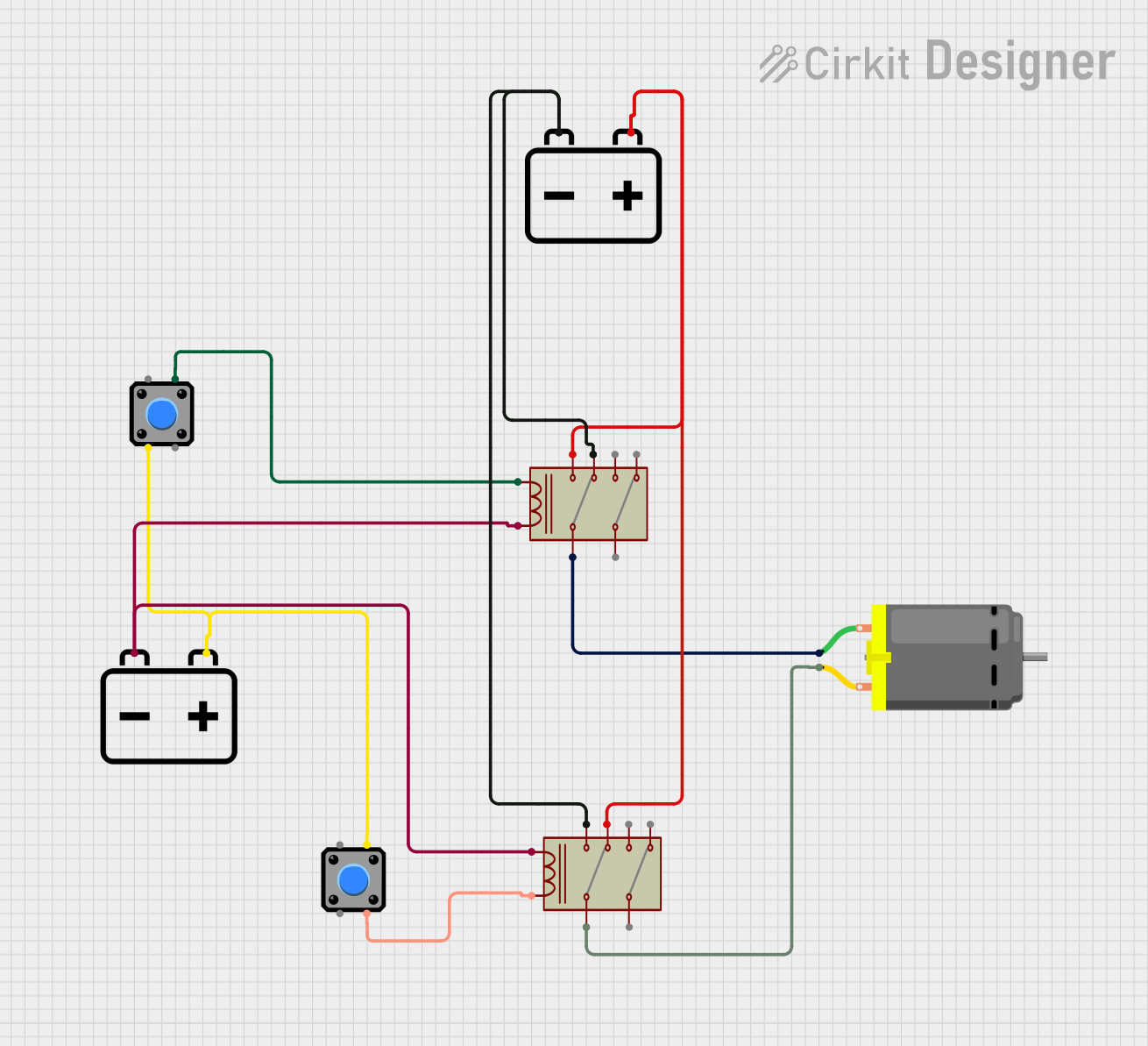
The circuit in question appears to be a control circuit utilizing relays to switch a DC motor on and off. The circuit includes two relays, two pushbuttons, two 12v batteries, and a DC motor. The relays are likely used to alternate the motor's connection between the two batteries, potentially reversing its direction or turning it off. The pushbuttons may be used to control the activation of the relay coils, thus controlling the motor's state.
Component List
Relay
- Description: A relay is an electrically operated switch that allows a low-power signal to control a higher power circuit. It typically consists of a coil, common terminals, normally open (NO) and normally closed (NC) contacts.
- Pins: Common 1, Common 2, Coil, NO 1, NC 1, NO 2, NC 2
Pushbutton
- Description: A pushbutton is a simple switch mechanism that controls some aspect of a machine or a process. It is typically used to complete or interrupt a circuit when pressed.
- Pins: Pin 1, Pin 2, Pin 3, Pin 4
DC Motor
- Description: A DC motor is a rotary electrical machine that converts direct current electrical energy into mechanical energy.
- Pins: pin 1, pin 2
12v Battery
- Description: A 12v battery is a storage device for electrical energy at 12 volts, commonly used to power circuits and various electrical components.
- Pins: + (positive), - (negative)
Wiring Details
Relay
- Common 1: Connected to DC Motor pin 1
- Coil: Connected to Pushbutton Pin 4 and 12v Battery negative terminal
- NO 1: Connected to 12v Battery positive terminal
- NC 1: Connected to 12v Battery negative terminal
Pushbutton
- Pin 2: Connected to 12v Battery positive terminal
- Pin 3: Connected to Relay Coil
- Pin 4: Connected to Relay Coil
DC Motor
- pin 1: Connected to Relay Common 1
- pin 2: Connected to Relay Common 1
12v Battery
- + (positive): Connected to Relay NO 1 and Pushbutton Pin 2
- - (negative): Connected to Relay Coil
Documented Code
The code provided is for a microcontroller, which does not seem to be directly connected to the circuit based on the provided information. The code is a template with empty setup and loop functions, which are placeholders for initialization and repetitive execution, respectively.
void setup() {
  // put your setup code here, to run once:

}

void loop() {
  // put your main code here, to run repeatedly:

}
The second file named "documentation.txt" is empty and does not contain any code or comments.
Please note that the documentation above is based on the provided information and assumes typical behavior of the components. The actual functionality of the circuit may vary depending on additional context and specific wiring details not included in the description.