
Arduino UNO R4 WiFi-Based Light-Responsive Motor Control System
View and Edit Project In Cirkit Designer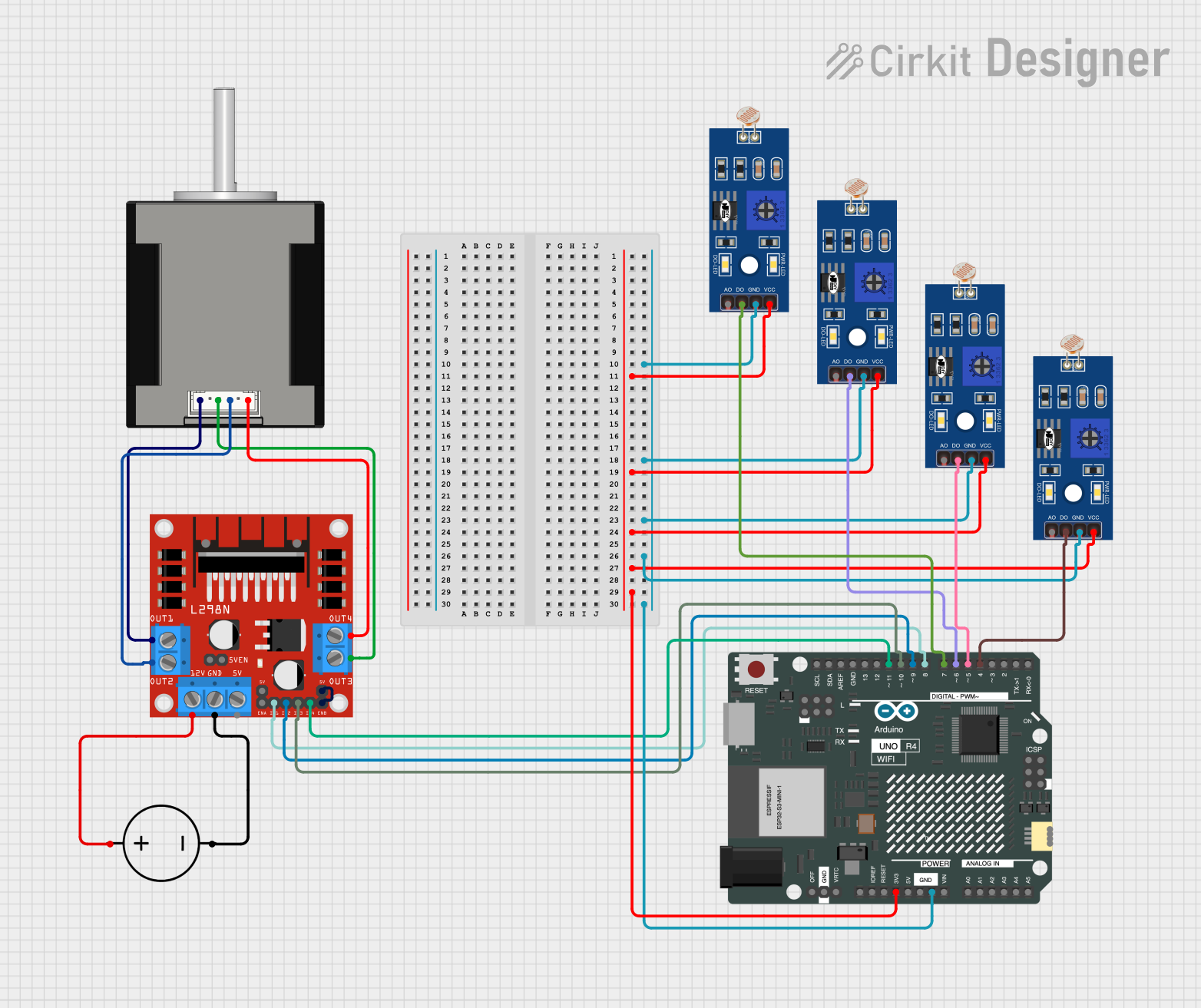
Circuit Documentation
Summary
This circuit involves an Arduino UNO R4 WiFi microcontroller, an L298N DC motor driver, a Nema 17 stepper motor, multiple Light Dependent Resistors (LDRs), and a DC power source. The Arduino UNO R4 WiFi is used to control the L298N motor driver, which in turn drives the Nema 17 stepper motor. The LDRs are used as sensors to provide input to the Arduino.
Component List
Arduino UNO R4 WiFi
- Description: A microcontroller board based on the ATmega328P, featuring WiFi connectivity.
- Pins: OFF, GND, VRTC, IIC0_SCL, IIC0_SDA, 3V3, GPIO 41, GPIO 0, GPIO 42, GPIO 43, GPIO 44, BOOT, IOREF, RESET, 5V, VIN, A0, A1, A2, A3, A4, A5, RSPCKA, CIPO, COPI, D0/RX, D1/TX, D2, D3, D4, D5, D6, D7, D8, D9, D10, D11, D12, D13, AREF, SDA, SCL
L298N DC Motor Driver
- Description: A dual H-Bridge motor driver that allows control of the speed and direction of two DC motors.
- Pins: OUT1, OUT2, 12V, GND, 5V, OUT3, OUT4, 5V-ENA-JMP-I, 5V-ENA-JMP-O, +5V-J1, +5V-J2, ENA, IN1, IN2, IN3, IN4, ENB
Nema 17 42-STH48
- Description: A stepper motor commonly used in 3D printers and CNC machines.
- Pins: A2 (black), A1 Green, B2 Red, B1 Blue
DC Power Source
- Description: Provides the necessary power for the circuit.
- Pins: Ground, Positive
LDR (Light Dependent Resistor)
- Description: A resistor whose resistance decreases with increasing incident light intensity.
- Pins: A0, D0, GND, VCC
Wiring Details
Arduino UNO R4 WiFi
- GND: Connected to GND of all LDRs.
- 3V3: Connected to VCC of all LDRs.
- D4: Connected to D0 of LDR.
- D5: Connected to D0 of LDR.
- D6: Connected to D0 of LDR.
- D7: Connected to D0 of LDR.
- D8: Connected to IN1 of L298N DC motor driver.
- D9: Connected to IN2 of L298N DC motor driver.
- D10: Connected to IN3 of L298N DC motor driver.
- D11: Connected to IN4 of L298N DC motor driver.
L298N DC Motor Driver
- OUT1: Connected to A2 (black) of Nema 17 stepper motor.
- OUT2: Connected to B2 Red of Nema 17 stepper motor.
- OUT3: Connected to A1 Green of Nema 17 stepper motor.
- OUT4: Connected to B1 Blue of Nema 17 stepper motor.
- 12V: Connected to Positive of DC Power Source.
- GND: Connected to Ground of DC Power Source.
- +5V-J2: Connected to ENB of L298N DC motor driver.
Nema 17 42-STH48
- A2 (black): Connected to OUT1 of L298N DC motor driver.
- B2 Red: Connected to OUT2 of L298N DC motor driver.
- A1 Green: Connected to OUT3 of L298N DC motor driver.
- B1 Blue: Connected to OUT4 of L298N DC motor driver.
DC Power Source
- Positive: Connected to 12V of L298N DC motor driver.
- Ground: Connected to GND of L298N DC motor driver.
LDR (Light Dependent Resistor)
- GND: Connected to GND of Arduino UNO R4 WiFi.
- VCC: Connected to 3V3 of Arduino UNO R4 WiFi.
- D0: Connected to D4, D5, D6, and D7 of Arduino UNO R4 WiFi.
Documented Code
Arduino UNO R4 WiFi Code
void setup() {
  // put your setup code here, to run once:

}

void loop() {
  // put your main code here, to run repeatedly:

}
This code is a basic template for the Arduino UNO R4 WiFi. The setup() function is where you initialize your settings, and the loop() function is where the main code runs repeatedly. You can add your specific logic to control the L298N motor driver and read inputs from the LDRs in these functions.