
Raspberry Pi Zero W Based Multi-Sensor Data Logger with LoRa Communication
View and Edit Project In Cirkit Designer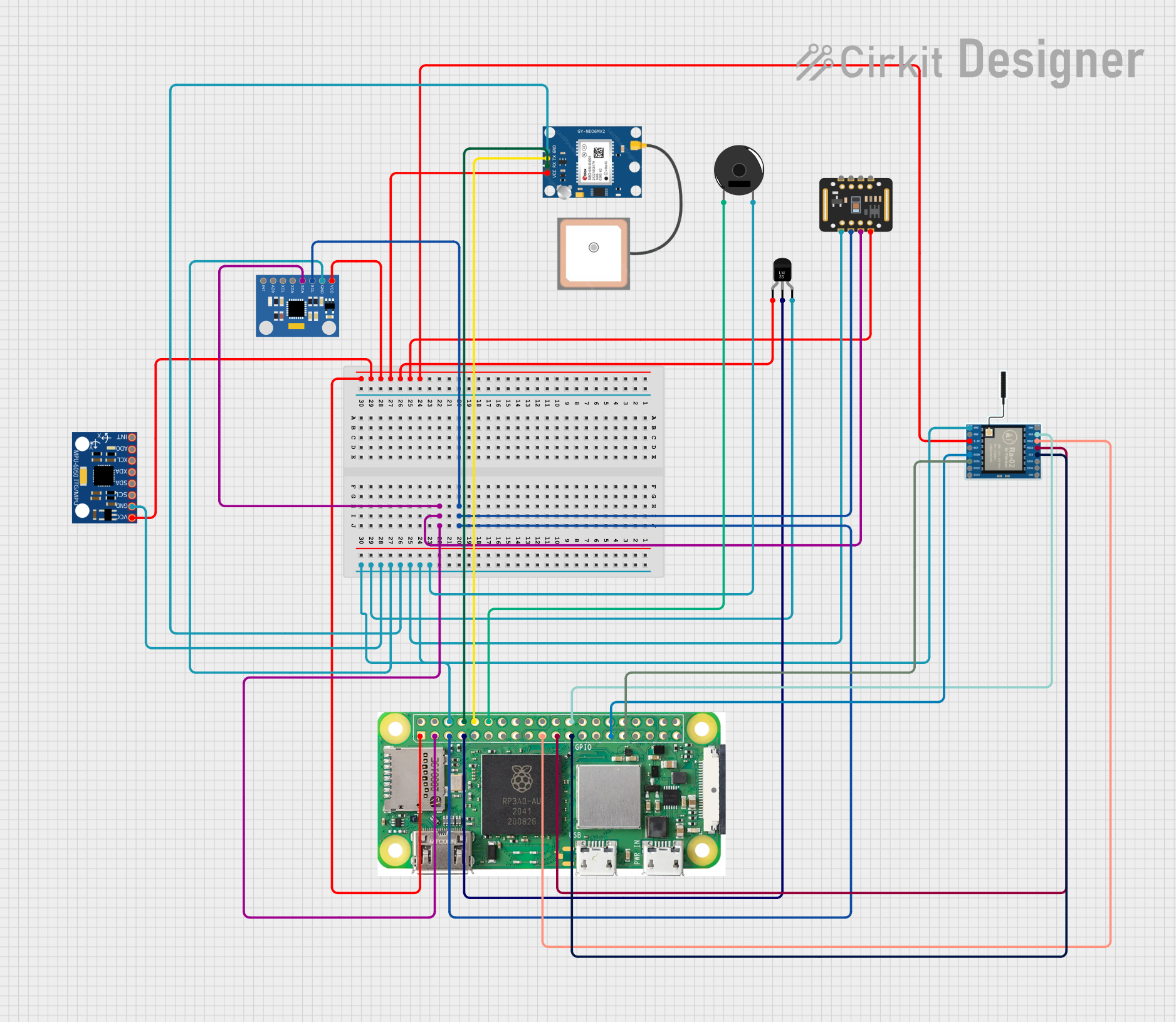
Circuit Documentation
Summary
The circuit in question is a multi-functional embedded system that integrates various sensors and communication modules with a Raspberry Pi Zero W as the central processing unit. The circuit is designed to measure temperature, motion (acceleration and gyroscope), heart rate, and oxygen saturation, as well as to provide GPS location tracking and LoRa wireless communication capabilities. The Raspberry Pi Zero W interfaces with the sensors and modules using GPIO pins for digital signals and I2C communication for data transfer.
Component List
Temperature Sensor (LM35)
- Description: A precision integrated-circuit temperature sensor with an output voltage linearly proportional to the Centigrade temperature.
- Pins: +Vs, Vout, GND
MPU-6050
- Description: A 6-axis motion tracking device that combines a 3-axis gyroscope and a 3-axis accelerometer.
- Pins: VCC, GND, SCL, SDA, XDA, XCL, AD0, INT
MAX30102
- Description: An integrated pulse oximetry and heart-rate monitor sensor solution.
- Pins: VIN, SDA, SCL, GND, RD, IRD, INT
Raspberry Pi Zero W
- Description: A low-cost, small-sized computer that is capable of digital computations and controlling other electronic components.
- Pins: 5V, 3V3, GPIO2 (SDA), GPIO 3 (SCL), GROUND, and various other GPIO pins.
MPU6050 Accelerometer + Gyroscope (Wokwi Compatible)
- Description: A sensor module that provides motion tracking through a 3-axis accelerometer and a 3-axis gyroscope.
- Pins: INT, AD0, XCL, XDA, SDA, SCL, GND, VCC
GPS NEO 6M
- Description: A GPS module that provides location tracking capabilities.
- Pins: VCC, RX, TX, GND
LoRa Ra-02 SX1278
- Description: A long-range wireless communication module based on the SX1278 chip.
- Pins: GND, NSS, MOSI, MISO, SCK, D105, DI04, 3.3V, RST, DI00, DI01, D102, DI03
Piezo Buzzer
- Description: An electronic device that emits sound when an electrical signal is applied.
- Pins: pin 1, pin 2
Wiring Details
Temperature Sensor (LM35)
- +Vs: Connected to 3V3 power supply.
- Vout: Connected to GPIO 04 of the Raspberry Pi Zero W.
- GND: Connected to the common ground.
MPU-6050
- VCC: Connected to 3V3 power supply.
- GND: Connected to the common ground.
- SCL: Connected to GPIO 3 (SCL) of the Raspberry Pi Zero W.
- SDA: Connected to GPIO 2 (SDA) of the Raspberry Pi Zero W.
MAX30102
- VIN: Connected to 3V3 power supply.
- SDA: Connected to GPIO 2 (SDA) of the Raspberry Pi Zero W.
- SCL: Connected to GPIO 3 (SCL) of the Raspberry Pi Zero W.
- GND: Connected to the common ground.
Raspberry Pi Zero W
- 3V3: Provides power to other components.
- GPIO 2 (SDA): Connected to SDA pins of MAX30102 and MPU6050 Accelerometer + Gyroscope.
- GPIO 3 (SCL): Connected to SCL pins of MAX30102 and MPU6050 Accelerometer + Gyroscope.
- GROUND: Common ground connection for various components.
- GPIO 14: Connected to RX pin of GPS NEO 6M.
- GPIO 15: Connected to TX pin of GPS NEO 6M.
- GPIO 18: Connected to pin 1 of Piezo Buzzer.
- GPIO 8: Connected to NSS pin of LoRa Ra-02 SX1278.
- GPIO 10: Connected to MOSI pin of LoRa Ra-02 SX1278.
- GPIO 9: Connected to MISO pin of LoRa Ra-02 SX1278.
- GPIO 11: Connected to SCK pin of LoRa Ra-02 SX1278.
- GPIO 5: Connected to DI00 pin of LoRa Ra-02 SX1278.
- GPIO 6: Connected to DI01 pin of LoRa Ra-02 SX1278.
MPU6050 Accelerometer + Gyroscope (Wokwi Compatible)
- VCC: Connected to 3V3 power supply.
- GND: Connected to the common ground.
- SDA: Connected to GPIO 2 (SDA) of the Raspberry Pi Zero W.
- SCL: Connected to GPIO 3 (SCL) of the Raspberry Pi Zero W.
GPS NEO 6M
- VCC: Connected to 3V3 power supply.
- RX: Connected to GPIO 14 of the Raspberry Pi Zero W.
- TX: Connected to GPIO 15 of the Raspberry Pi Zero W.
- GND: Connected to the common ground.
LoRa Ra-02 SX1278
- 3.3V: Connected to 3V3 power supply.
- GND: Connected to the common ground.
- NSS: Connected to GPIO 8 of the Raspberry Pi Zero W.
- MOSI: Connected to GPIO 10 of the Raspberry Pi Zero W.
- MISO: Connected to GPIO 9 of the Raspberry Pi Zero W.
- SCK: Connected to GPIO 11 of the Raspberry Pi Zero W.
- DI00: Connected to GPIO 5 of the Raspberry Pi Zero W.
- DI01: Connected to GPIO 6 of the Raspberry Pi Zero W.
Piezo Buzzer
- pin 1: Connected to GPIO 18 of the Raspberry Pi Zero W.
- pin 2: Connected to the common ground.
Documented Code
No code has been provided for the microcontrollers in the circuit. The Raspberry Pi Zero W would typically be programmed using a high-level language such as Python, and the code would be responsible for initializing and reading data from the sensors, controlling the buzzer, and managing communication via the GPS and LoRa modules. Without the specific code, we cannot document the software aspect of this circuit.