
Arduino-Controlled Dual Motor System with IR Sensor Feedback
View and Edit Project In Cirkit Designer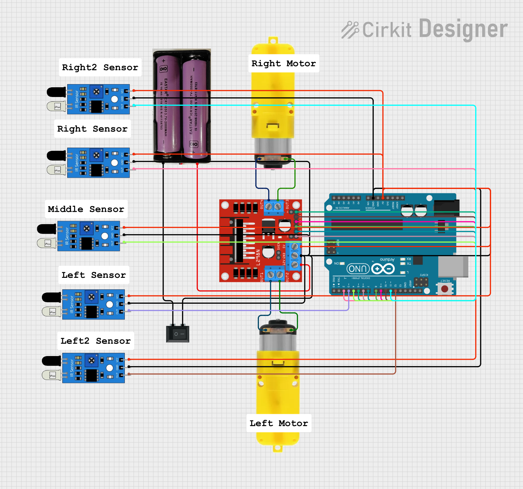
Circuit Documentation
Summary
This circuit is designed to control two motors with reducers using an L298N DC motor driver, which is interfaced with an Arduino UNO microcontroller. The circuit also includes multiple infrared (IR) sensors for input and a rocker switch (SPST) to control the power supply. The power supply is a 7.4V battery. The Arduino UNO is responsible for processing the signals from the IR sensors and controlling the motor driver, which in turn controls the motors.
Component List
Arduino UNO
- Microcontroller board based on the ATmega328P
- It has 14 digital input/output pins, 6 analog inputs, a 16 MHz quartz crystal, a USB connection, a power jack, an ICSP header, and a reset button.
Motor with Reducer (x2)
- A DC motor with a gear reduction mechanism
- Operates between 3 - 6 V
L298N DC Motor Driver
- A dual H-bridge motor driver
- It can drive two DC motors or one stepper motor
- It has two enable inputs and four direction inputs
Rocker Switch (SPST)
- A single-pole single-throw (SPST) switch
- Used to connect or disconnect the circuit from the power supply
7.4V Battery
- Provides the power supply for the circuit
IR Sensor (x6)
- An infrared sensor capable of detecting obstacles or receiving IR signals
- It has an output pin along with VCC and GND for power
Comments
- There are several comment components listed, which are likely placeholders for notes or labels within the circuit design software.
Wiring Details
Arduino UNO
- 5V and GND pins are used to power the IR sensors and the L298N motor driver.
- Digital pins D2 to D12 are used to interface with the IR sensors and the L298N motor driver.
Motor with Reducer
- Each motor is connected to the L298N motor driver's output pins (OUT1, OUT2, OUT3, OUT4).
L298N DC Motor Driver
- 5V pin is connected to the IR sensors and the Arduino's 5V pin.
- GND pin is connected to the IR sensors, the Arduino's GND pin, and one side of the rocker switch.
- IN1 to IN4 pins are connected to the Arduino's digital pins D7 to D10 for motor control signals.
- ENA and ENB pins are connected to the Arduino's digital pins D6 and D5 for enabling the motor driver.
- OUT1 to OUT4 pins are connected to the motors.
- 12V pin is connected to the 7.4V battery's positive terminal.
Rocker Switch (SPST)
- One pin is connected to the 7.4V battery's negative terminal.
- The other pin is connected to the L298N motor driver's GND.
IR Sensors
- VCC pins are connected to the L298N motor driver's 5V pin.
- GND pins are connected to the L298N motor driver's GND pin.
- OUT pins are connected to the Arduino's digital pins D2 to D4 and D11 to D12.
Documented Code
Arduino UNO - sketch.ino
void setup() {
  // put your setup code here, to run once:

}

void loop() {
  // put your main code here, to run repeatedly:

}
Arduino UNO - documentation.txt
(No additional documentation provided for the code)
(Note: The provided code is a template and does not contain any functional code for controlling the motors or reading the IR sensors. Additional programming will be required to achieve the desired functionality of the circuit.)