Cirkit Designer
Your all-in-one circuit design IDE
Home /
Project Documentation
Arduino-Powered Security System with Wi-Fi Connectivity and Thermal Imaging

Circuit Documentation
Summary
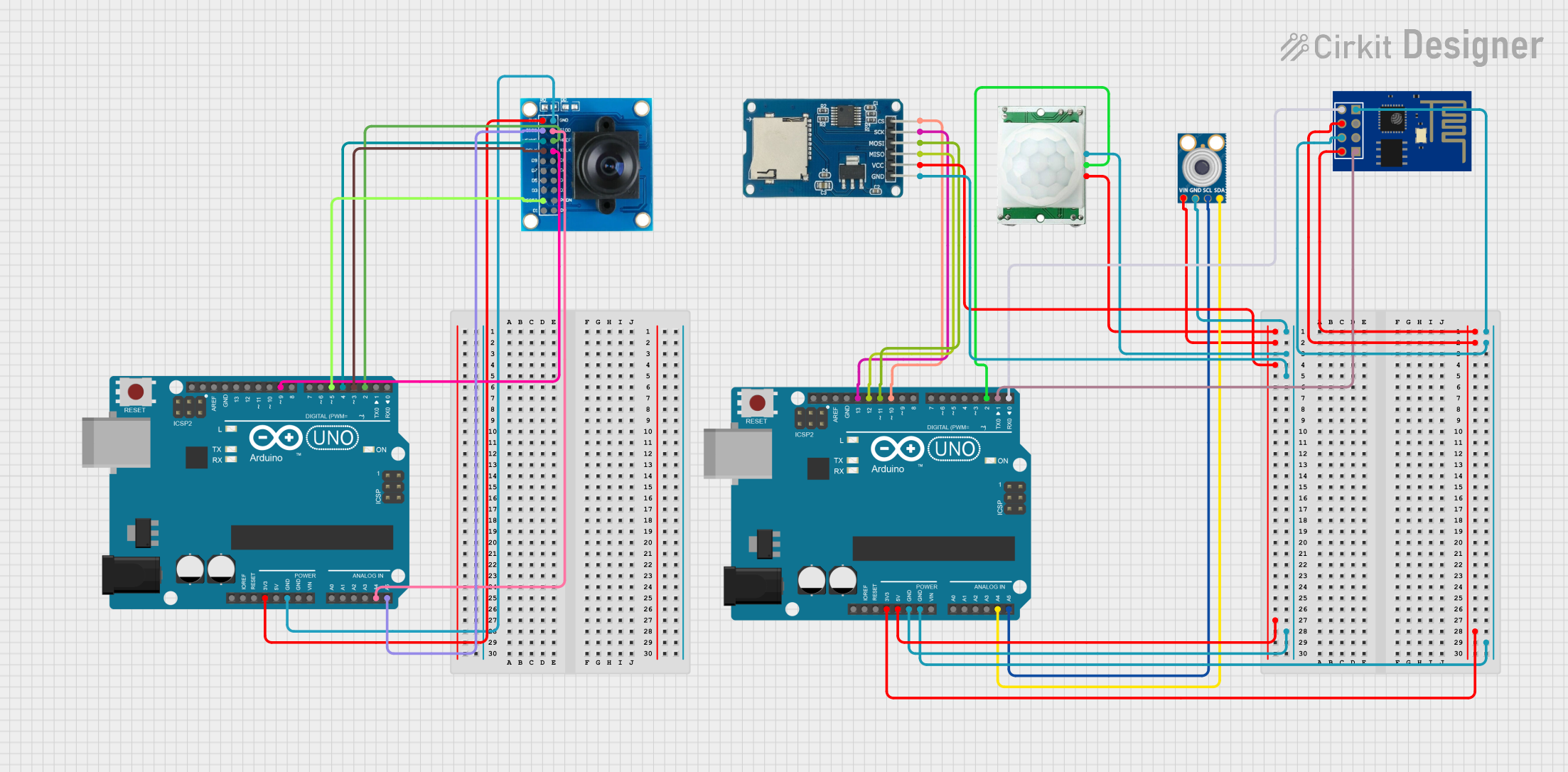
This circuit integrates various components to perform multiple functions. It includes two Arduino UNO microcontrollers, a mlx90614 infrared temperature sensor, an OV7725 camera module, a PIR motion sensor, an ESP8266 ESP-01 WiFi module, and a Micro SD Card Module. The circuit is designed to capture and process images, detect motion, measure temperature, store data, and communicate over WiFi.
Component List
Arduino UNO
- Microcontroller board based on the ATmega328P
- It has 14 digital input/output pins, 6 analog inputs, a 16 MHz quartz crystal, a USB connection, a power jack, an ICSP header, and a reset button.
mlx90614
- An infrared temperature sensor for non-contact temperature measurements.
OV7725
- A camera module that captures images and provides a digital video stream.
PIR/Motion Sensor
- A passive infrared sensor that detects motion by measuring changes in the infrared levels emitted by surrounding objects.
ESP8266 ESP-01 WiFi Module
- A self-contained SOC with integrated TCP/IP protocol stack that can give any microcontroller access to your WiFi network.
Micro SD Card Module
- A module that allows a microcontroller to read from and write to a micro SD card.
Wiring Details
Arduino UNO
- 5V pin is connected to the VCC of mlx90614, PIR/Motion Sensor, and Micro SD Card Module.
- GND pin is connected to the GND of mlx90614, PIR/Motion Sensor, Micro SD Card Module, and ESP8266 ESP-01 WiFi Module.
- A4 (SDA) pin is connected to the SDA of mlx90614.
- A5 (SCL) pin is connected to the SCL of mlx90614.
- D13 pin is connected to the sck of Micro SD Card Module.
- D12 pin is connected to the miso of Micro SD Card Module.
- D11 pin is connected to the mosi of Micro SD Card Module.
- D10 pin is connected to the cs of Micro SD Card Module.
- D2 pin is connected to the OUTPUT of PIR/Motion Sensor.
- D1 (TX) pin is connected to the RXD of ESP8266 ESP-01 WiFi Module.
- D0 (RX) pin is connected to the TXD of ESP8266 ESP-01 WiFi Module.
mlx90614
- SDA pin is connected to the SDA (A4) of Arduino UNO.
- SCL pin is connected to the SCL (A5) of Arduino UNO.
- GND pin is connected to the GND of Arduino UNO.
- VIN pin is connected to the 5V of Arduino UNO.
OV7725
- 3V3 pin is connected to the 3.3V of the second Arduino UNO.
- GND pin is connected to the GND of the second Arduino UNO.
- SIOC pin is connected to the A5 of the second Arduino UNO.
- SIOD pin is connected to the A4 of the second Arduino UNO.
- VSYNC pin is connected to the D4 of the second Arduino UNO.
- HREF pin is connected to the D2 of the second Arduino UNO.
- PCLK pin is connected to the D3 of the second Arduino UNO.
- XCLK pin is connected to the D9 of the second Arduino UNO.
- RESET pin is connected to the D5 of the second Arduino UNO.
PIR/Motion Sensor
- VCC pin is connected to the 5V of Arduino UNO.
- GND pin is connected to the GND of Arduino UNO.
- OUTPUT pin is connected to the D2 of Arduino UNO.
ESP8266 ESP-01 WiFi Module
- VCC pin is connected to the 3.3V of Arduino UNO.
- CH_PD pin is connected to the 3.3V of Arduino UNO.
- RST pin is connected to the GND of Arduino UNO.
- GND pin is connected to the GND of Arduino UNO.
- TXD pin is connected to the D0 (RX) of Arduino UNO.
- RXD pin is connected to the D1 (TX) of Arduino UNO.
Micro SD Card Module
- cs pin is connected to the D10 of Arduino UNO.
- sck pin is connected to the D13 of Arduino UNO.
- mosi pin is connected to the D11 of Arduino UNO.
- miso pin is connected to the D12 of Arduino UNO.
- vcc pin is connected to the 5V of Arduino UNO.
- gnd pin is connected to the GND of Arduino UNO.
Documented Code
Arduino UNO (Primary)
void setup() {
  // put your setup code here, to run once:

}

void loop() {
  // put your main code here, to run repeatedly:

}
Filename: sketch.ino
Arduino UNO (Secondary)
void setup() {
  // put your setup code here, to run once:

}

void loop() {
  // put your main code here, to run repeatedly:

}
Filename: sketch.ino
Note: The actual functionality of the code is not provided in the input, hence the setup and loop functions are empty. The user should fill in the code according to the specific requirements of the circuit.