
Wi-Fi Controlled IR Transmitter and Receiver using NodeMCU ESP8266
View and Edit Project In Cirkit Designer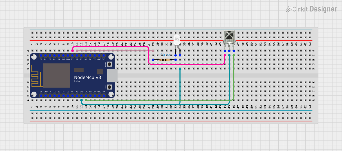
Circuit Documentation
Summary
This circuit involves a NodeMCU V3 ESP8266 microcontroller, an IR receiver, an LED, and a resistor. The NodeMCU is used to receive IR signals via the IR receiver and control the LED based on the received signals. The resistor is used to limit the current flowing through the LED to prevent damage.
Component List
NodeMCU V3 ESP8266
- Description: A microcontroller with built-in Wi-Fi capabilities.
- Pins: A0, GND, VU, S3, S2, S1, SC, S0, SK, 3V3, EN, RST, Vin, D0, D1, D2, D3, D4, D5, D6, D7, D8, RX, TX
LED: Two Pin (white)
- Description: A white LED with two pins: cathode and anode.
- Pins: cathode, anode
Resistor
- Description: A resistor with a resistance of 100 Ohms.
- Pins: pin1, pin2
- Properties:
- Resistance: 100 Ohms
VS1838B IR Receiver
- Description: An IR receiver used to receive infrared signals.
- Pins: OUT, GND, VCC
Wiring Details
NodeMCU V3 ESP8266
- D5 is connected to OUT of the VS1838B IR Receiver.
- D6 is connected to pin1 of the Resistor.
- GND is connected to anode of the LED and GND of the VS1838B IR Receiver.
- 3V3 is connected to VCC of the VS1838B IR Receiver.
LED: Two Pin (white)
- cathode is connected to pin2 of the Resistor.
- anode is connected to GND of the NodeMCU V3 ESP8266.
Resistor
- pin1 is connected to D6 of the NodeMCU V3 ESP8266.
- pin2 is connected to cathode of the LED.
VS1838B IR Receiver
- OUT is connected to D5 of the NodeMCU V3 ESP8266.
- GND is connected to GND of the NodeMCU V3 ESP8266.
- VCC is connected to 3V3 of the NodeMCU V3 ESP8266.
Documented Code
SimpleSender.ino
/*
 * SimpleSender.cpp
 *
 *  Demonstrates sending IR codes in standard format with address and command
 *  An extended example for sending can be found as SendDemo.
 *
 *  Copyright (C) 2020-2022  Armin Joachimsmeyer
 *  armin.joachimsmeyer@gmail.com
 *
 *  This file is part of Arduino-IRremote https://github.com/Arduino-IRremote/Arduino-IRremote.
 *
 *  MIT License
 */
#include <Arduino.h>

#if !defined(ARDUINO_ESP32C3_DEV) // This is due to a bug in RISC-V compiler, which requires unused function sections :-(.
#define DISABLE_CODE_FOR_RECEIVER // Disables static receiver code like receive timer ISR handler and static IRReceiver and irparams data. Saves 450 bytes program memory and 269 bytes RAM if receiving functions are not required.
#endif
//#define SEND_PWM_BY_TIMER         // Disable carrier PWM generation in software and use (restricted) hardware PWM.
//#define USE_NO_SEND_PWM           // Use no carrier PWM, just simulate an active low receiver signal. Overrides SEND_PWM_BY_TIMER definition

/*
 * This include defines the actual pin number for pins like IR_RECEIVE_PIN, IR_SEND_PIN for many different boards and architectures
 */
#include "PinDefinitionsAndMore.h"
#include <IRremote.hpp> // include the library

void setup() {
    pinMode(LED_BUILTIN, OUTPUT);

    Serial.begin(115200);
    while (!Serial)
        ; // Wait for Serial to become available. Is optimized away for some cores.

    // Just to know which program is running on my Arduino
    Serial.println(F("START " __FILE__ " from " __DATE__ "\r\nUsing library version " VERSION_IRREMOTE));
    Serial.print(F("Send IR signals at pin "));
    Serial.println(IR_SEND_PIN);

    /*
     * The IR library setup. That's all!
     */
    IrSender.begin(); // Start with IR_SEND_PIN -which is defined in PinDefinitionsAndMore.h- as send pin and enable feedback LED at default feedback LED pin
    disableLEDFeedback(); // Disable feedback LED at default feedback LED pin
}

/*
 * Set up the data to be sent.
 * For most protocols, the data is build up with a constant 8 (or 16 byte) address
 * and a variable 8 bit command.
 * There are exceptions like Sony and Denon, which have 5 bit address.
 */
uint8_t sCommand = 0x34;
uint8_t sRepeats = 0;

void loop() {
    /*
     * Print current send values
     */
    Serial.println();
    Serial.print(F("Send now: address=0x00, command=0x"));
    Serial.print(sCommand, HEX);
    Serial.print(F(", repeats="));
    Serial.print(sRepeats);
    Serial.println();

    Serial.println(F("Send standard NEC with 8 bit address"));
    Serial.flush();

    // Receiver output for the first loop must be: Protocol=NEC Address=0x102 Command=0x34 Raw-Data=0xCB340102 (32 bits)
    //IrSender.sendNEC(0x00, sCommand, sRepeats);
    IrSender.sendSony(0x10, 0x15, 2, 12);

    /*
     * If you want to send a raw HEX value directly like e.g. 0xCB340102 you must use sendNECRaw()
     */
//    Serial.println(F("Send 32 bit LSB 0xCB340102 with NECRaw()"));
//    IrSender.sendNECRaw(0xCB340102, sRepeats);

    /*
     * If you want to send an "old" MSB HEX value used by IRremote versions before 3.0 like e.g. 0x40802CD3 you must use sendNECMSB()
     */
//    Serial.println(F("Send old 32 bit MSB 0x40802CD3 with sendNECMSB()"));
//    IrSender.sendNECMSB(0x40802CD3, 32, sRepeats);

    /*
     * Increment send values
     */
    /*
    sCommand += 0x11;
    sRepeats++;
    // clip repeats at 4
    if (sRepeats > 4) {
        sRepeats = 4;
    }
    */
    delay(10000);  // delay must be greater than 5 ms (RECORD_GAP_MICROS), otherwise the receiver sees it as one long signal
}
Documentation.txt
IR Receiver
VCC (IR Receiver) -> 3V3 (NodeMCU)
GND (IR Receiver) -> GND (NodeMCU)
OUT (IR Receiver) -> D5 (NodeMCU)

IR LED
LED Cathode -> Resistor Pin 2
Resistor Pin 1 -> NodeMCU D6
LED Anode -> NodeMCU GND