Arduino Nano Controlled Robotic Cleaner with Ultrasonic Sensors and I2C LCD Interface
Circuit Documentation
Summary
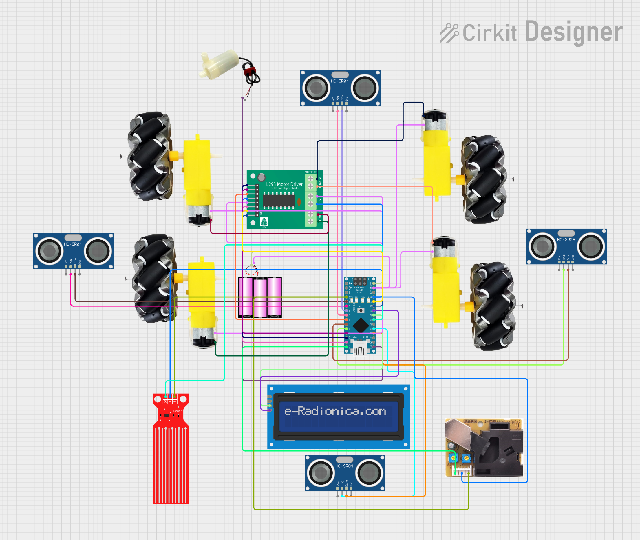
This circuit is designed to control a robotic cleaning system equipped with multiple sensors and actuators. The system is powered by a 12V battery and is controlled by an Arduino Nano microcontroller. The circuit includes motor and wheel assemblies for movement, a 5V mini water pump for wet cleaning, water level and dust sensors for environmental monitoring, and multiple HC-SR04 ultrasonic sensors for obstacle detection and navigation. A L293D motor driver is used to control the motors, and an I2C LCD screen provides a user interface for mode selection and status display.
Component List
Battery 12V
- Description: Provides the main power source for the circuit.
- Pins:
+,-
Motor and Wheels (4 instances)
- Description: Actuators for the robotic system's movement.
- Pins:
vcc,GND
5V Mini Water Pump
- Description: Used for wet cleaning by spraying water.
- Pins:
positive pin,negative pin
Water Level Sensor
- Description: Monitors the water level in the tank to ensure there is enough water for wet cleaning.
- Pins:
SIG,VCC,GND
Dust Sensor
- Description: Measures the dust level in the environment to assess cleaning efficiency.
- Pins:
D8,5V,GND
HC-SR04 Ultrasonic Sensor (4 instances)
- Description: Used for distance measurement and obstacle detection.
- Pins:
VCC,TRIG,ECHO,GND
L293D Motor Driver
- Description: Drives the motors based on control signals from the Arduino Nano.
- Pins:
B1,B2,A1,EN_B,EN_A,A2,GND,VCC,+,-,MPIN_1,MPIN_2,MPIN_3,MPIN_4
Arduino Nano
- Description: The main microcontroller unit that processes sensor data and controls actuators.
- Pins:
D1/TX,D0/RX,RESET,GND,D2,D3,D4,D5,D6,D7,D8,D9,D10,D11/MOSI,D12/MISO,VIN,5V,A7,A6,A5,A4,A3,A2,A1,A0,AREF,3V3,D13/SCK
LCD Screen 16x2 I2C
- Description: Displays the status and mode of the robotic system.
- Pins:
SCL,SDA,VCC,GND
Wiring Details
Battery 12V
+to Arduino NanoVIN-to common ground net
Motor and Wheels
vccto L293D Motor DriverMPIN_x(where x is the respective motor pin number)GNDto common ground net
5V Mini Water Pump
positive pinto Arduino NanoD13/SCKnegative pinto common ground net
Water Level Sensor
SIGto Arduino NanoA3VCCto common 5V netGNDto common ground net
Dust Sensor
D8to Arduino NanoD12/MISO5Vto common 5V netGNDto common ground net
HC-SR04 Ultrasonic Sensor
VCCto common 5V netTRIGto respective Arduino Nano digital pins (D3,D5,D8,A1)ECHOto respective Arduino Nano digital pins (D2,D4,D7,A0)GNDto common ground net
L293D Motor Driver
B1,B2,A1,A2to respective Arduino Nano pins (A6,A7,D10,D9)EN_B,EN_Ato Arduino Nano pins (D11/MOSI,D6)GNDto common ground netVCC,+to common 5V net-to common ground net
Arduino Nano
VINconnected to Battery 12V+GNDto common ground net5Vto common 5V net- Digital and analog pins connected as per the code and sensor/actuator requirements
LCD Screen 16x2 I2C
SCLto Arduino NanoA5SDAto Arduino NanoA4VCCto common 5V netGNDto common ground net
Documented Code
#include <NewPing.h>    // Import libraries for ultrasonic sensors
#include <LiquidCrystal_I2C.h>     // I2C LCD library
#include <Wire.h>                 // I2C library

// Initialize pin numbers for ultrasonic sensors and motor control
const int echo_L = 2; const int trig_L = 3;
const int echo_M = 4; const int trig_M = 5;
const int echo_R = 7; const int trig_R = 8;
const int echo_Crack = A0; const int trig_Crack = A1;
const int dustSensorPin = A2; // Dust sensor
const int waterLevelPin = A3;
const int L1 = 6; const int L2 = 9;
const int R1 = 10; const int R2 = 11;
const int pump = 13; // Pump control for wet cleaning

// Additional variables and constants
int motor_speed = 255;
int max_distance = 200;
int distance_L = 0; int distance_M = 0;
int distance_R = 0; int distance_Crack = 0;
bool isWetCleaning = false;
bool isWaterLow = false;
unsigned long lastPumpTime = 0;

// Initialize ultrasonic sensors and LCD
NewPing sonar_L(trig_L, echo_L, max_distance);
NewPing sonar_M(trig_M, echo_M, max_distance);
NewPing sonar_R(trig_R, echo_R, max_distance);
NewPing sonar_Crack(trig_Crack, echo_Crack, max_distance);
LiquidCrystal_I2C lcd(0x27, 16, 2);

void setup() {
  // Setup pin modes and initial states
  pinMode(L1, OUTPUT); pinMode(L2, OUTPUT);
  pinMode(R1, OUTPUT); pinMode(R2, OUTPUT);
  pinMode(pump, OUTPUT);
  digitalWrite(L1, LOW); digitalWrite(L2, LOW);
  digitalWrite(R1, LOW); digitalWrite(R2, LOW);
  digitalWrite(pump, LOW);
  lcd.begin(16, 2); lcd.print("Choose Mode");
  Serial.begin(9600);
  delay(2000);
}

void loop() {
  // Mode selection and sensor reading logic
  // Movement control and wet cleaning logic
  // Dust detection and water level checking
  // Functions for moving the robot and controlling the pump
}

// Functions for reading sensors and controlling actuators
// Detailed function implementations are omitted for brevity
The code provided is a high-level overview of the embedded software running on the Arduino Nano. It includes initialization of sensors and actuators, setup of pin modes, and the main loop with logic for mode selection, movement control, sensor reading, and actuator control. Functions for reading sensors, moving the robot, and controlling the pump are declared and used within the loop.