Cirkit Designer
Your all-in-one circuit design IDE
Home /
Project Documentation
Arduino UNO-Based Smart Weather Station with RFID and Battery Power
Circuit Documentation
Summary
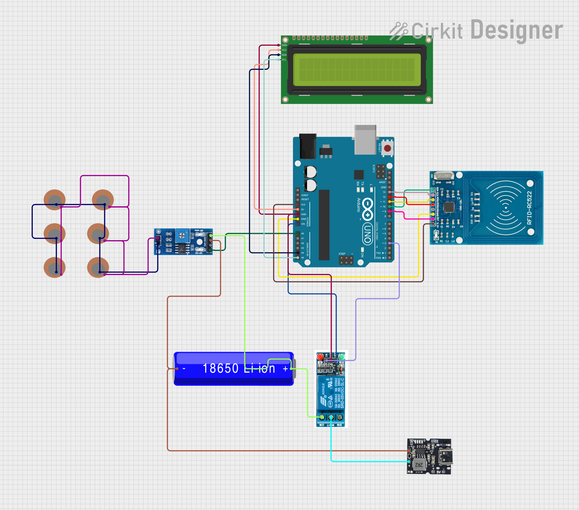
This document provides a detailed overview of a circuit that integrates an Arduino UNO microcontroller with various sensors and modules, including an RFID reader, a rain/snow sensor, a 16x2 I2C LCD, a 5V relay, and multiple piezo sensors. The circuit is powered by a 18650 Li-ion battery and a Type-C power bank module. The Arduino UNO is programmed to interact with these components to perform specific tasks.
Component List
Arduino UNO
- Description: A microcontroller board based on the ATmega328P.
- Pins: UNUSED, IOREF, Reset, 3.3V, 5V, GND, Vin, A0, A1, A2, A3, A4, A5, SCL, SDA, AREF, D13, D12, D11, D10, D9, D8, D7, D6, D5, D4, D3, D2, D1, D0
RFID-RC522
- Description: A low-cost RFID reader module.
- Pins: VCC (3.3V), RST, GND, IRQ, MISO, MOSI, SCK, SDA
Type-C Power Bank Module
- Description: A module to provide power from a Type-C USB connection.
- Pins: Gnd, +Ve (Bat), +5v
Piezo Sensor
- Description: A sensor that generates a voltage when deformed.
- Pins: +, -
Rain/Snow Sensor - Board
- Description: A sensor to detect rain or snow.
- Pins: 1, 2, A0 (Analog), D0 (Digital), GND, VCC (5V)
18650 Li-ion Battery
- Description: A rechargeable lithium-ion battery.
- Pins: -, +
16x2 I2C LCD
- Description: A 16x2 character LCD with I2C interface.
- Pins: GND, VCC, SDA, SCL
5V Relay
- Description: A relay module that operates at 5V.
- Pins: Normally Open, Common terminal, Normally Closed, In, GND, VCC
Wiring Details
Arduino UNO
- 3.3V connected to VCC (3.3V) of RFID-RC522
- 5V connected to VCC of 16x2 I2C LCD
- GND connected to GND of 5V relay, 16x2 I2C LCD, and RFID-RC522
- Vin connected to VCC of 5V relay
- A0 connected to A0 (Analog) of Rain/Snow Sensor - Board
- A4 connected to SDA of 16x2 I2C LCD
- A5 connected to SCL of 16x2 I2C LCD
- D13 connected to SCK of RFID-RC522
- D12 connected to MISO of RFID-RC522
- D11 connected to MOSI of RFID-RC522
- D10 connected to SDA of RFID-RC522
- D9 connected to RST of RFID-RC522
- D3 connected to In of 5V relay
RFID-RC522
- VCC (3.3V) connected to 3.3V of Arduino UNO
- GND connected to GND of Arduino UNO
- SCK connected to D13 of Arduino UNO
- MISO connected to D12 of Arduino UNO
- MOSI connected to D11 of Arduino UNO
- SDA connected to D10 of Arduino UNO
- RST connected to D9 of Arduino UNO
Type-C Power Bank Module
- Gnd connected to - of 18650 Li-ion Battery and GND of Rain/Snow Sensor - Board
- +Ve (Bat) connected to Common terminal of 5V relay
Piezo Sensors
- + of all piezo sensors connected to 1 of Rain/Snow Sensor - Board
- - of all piezo sensors connected to 2 of Rain/Snow Sensor - Board
Rain/Snow Sensor - Board
- A0 (Analog) connected to A0 of Arduino UNO
- GND connected to Gnd of Type-C Power Bank Module
- VCC (5V) connected to Normally Open of 5V relay
18650 Li-ion Battery
- - connected to Gnd of Type-C Power Bank Module and GND of Rain/Snow Sensor - Board
- + connected to Normally Open of 5V relay and VCC (5V) of Rain/Snow Sensor - Board
16x2 I2C LCD
- VCC connected to 5V of Arduino UNO
- GND connected to GND of Arduino UNO
- SDA connected to A4 of Arduino UNO
- SCL connected to A5 of Arduino UNO
5V Relay
- GND connected to GND of Arduino UNO
- VCC connected to Vin of Arduino UNO
- In connected to D3 of Arduino UNO
- Common terminal connected to +Ve (Bat) of Type-C Power Bank Module
- Normally Open connected to + of 18650 Li-ion Battery and VCC (5V) of Rain/Snow Sensor - Board
Documented Code
Arduino UNO Code (sketch.ino)
void setup() {
  // put your setup code here, to run once:

}

void loop() {
  // put your main code here, to run repeatedly:

}
This code is a basic template for the Arduino UNO. The setup() function is where you initialize your components and the loop() function is where you place the main logic that runs repeatedly.