
Arduino Nano-Controlled Robotic Vehicle with NRF24L01 Wireless Communication
View and Edit Project In Cirkit Designer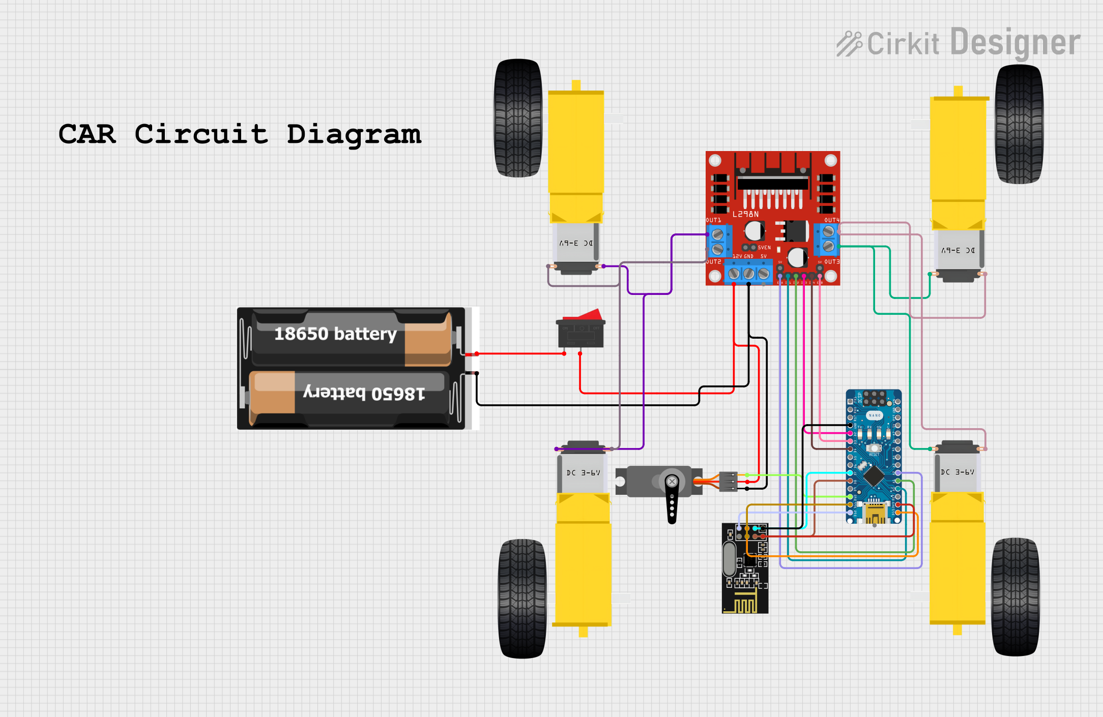
Circuit Documentation
Summary
This circuit integrates an Arduino Nano microcontroller with a variety of components including a DC motor driver, gearmotors for wheels, a servo motor, a wireless communication module (NRF24L01), and a power supply consisting of 2x 18650 batteries with a rocker switch. The Arduino Nano is responsible for controlling the motors through the L298N motor driver, interfacing with the NRF24L01 module for wireless communication, and driving a servo motor. The circuit is designed to be a part of a remotely controlled vehicle with wireless capabilities.
Component List
Arduino Nano
- Microcontroller board based on the ATmega328P
- It has a variety of digital and analog I/O pins.
Gearmotor DC Wheels (Right and Left)
- DC motors with gear reduction used for driving the wheels of the vehicle.
Servo
- A small rotary actuator that has built-in control circuitry.
L298N DC Motor Driver
- An integrated circuit that allows control of two DC motors simultaneously.
- It can drive motors with a voltage between 5V and 35V at up to 2A each.
2x 18650 Batteries
- Rechargeable lithium-ion cells used to power the circuit.
Rocker Switch
- A simple on-off switch that controls the power supply to the circuit.
NRF24L01
- A wireless transceiver module that operates in the 2.4 GHz band.
- It is used for wireless communication between the vehicle and a remote controller.
Wiring Details
Arduino Nano
- GND connected to NRF24L01 GND, L298N GND, and Servo GND.
- D2 connected to L298N IN3.
- D3 connected to L298N ENB.
- D4 connected to L298N IN4.
- D7 connected to NRF24L01 CE.
- D8 connected to NRF24L01 CSN.
- D10 connected to Servo PWM.
- D11/MOSI connected to NRF24L01 MOSI.
- D12/MISO connected to NRF24L01 MISO.
- A2 connected to L298N ENA.
- A1 connected to L298N IN2.
- A0 connected to L298N IN1.
- 3V3 connected to NRF24L01 VCC (3V).
- D13/SCK connected to NRF24L01 SCK.
Gearmotor DC Wheels (Right and Left)
- Right Motor PIN1 connected to L298N OUT4.
- Right Motor PIN2 connected to L298N OUT3.
- Left Motor PIN1 connected to L298N OUT2.
- Left Motor PIN2 connected to L298N OUT1.
Servo
- PWM connected to Arduino Nano D10.
- VCC connected to Rocker Switch pin 2 and L298N 12V.
- GND connected to 2x 18650 gnd and L298N GND.
L298N DC Motor Driver
- GND connected to Arduino Nano GND, Servo GND, and 2x 18650 gnd.
- 12V connected to Servo VCC and Rocker Switch pin 2.
- 5V (if used) would be connected to a 5V supply.
- ENA, IN1, IN2, IN3, IN4, ENB connected to various pins on the Arduino Nano for control signals.
- OUT1, OUT2, OUT3, OUT4 connected to the gearmotors.
2x 18650 Batteries
- vcc connected to Rocker Switch pin 1.
- gnd connected to Servo GND and L298N GND.
Rocker Switch
- Pin 1 connected to 2x 18650 vcc.
- Pin 2 connected to Servo VCC and L298N 12V.
NRF24L01
- GND connected to Arduino Nano GND.
- CE connected to Arduino Nano D7.
- CSN connected to Arduino Nano D8.
- MOSI connected to Arduino Nano D11/MOSI.
- MISO connected to Arduino Nano D12/MISO.
- VCC (3V) connected to Arduino Nano 3V3.
- SCK connected to Arduino Nano D13/SCK.
Documented Code
Arduino Nano Code (sketch.ino)
void setup() {
  // put your setup code here, to run once:

}

void loop() {
  // put your main code here, to run repeatedly:

}
Note: The provided code is a template and does not contain any functional code. It needs to be populated with the logic to control the motors, read sensors, and handle wireless communication.