Cirkit Designer
Your all-in-one circuit design IDE
Home /
Project Documentation
ESP32 Solar-Powered Battery Monitoring System with Voltage and Current Sensors
Circuit Documentation
Summary
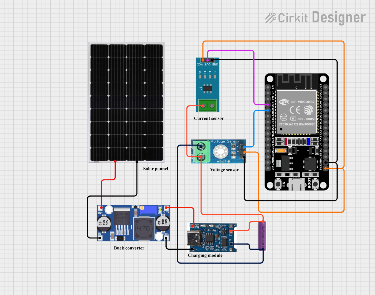
This document provides a detailed overview of a circuit that includes an ESP32 microcontroller, various sensors, a battery charger, a buck converter, a 3.7V battery, and a solar panel. The circuit is designed to monitor voltage and current, charge a battery using solar power, and provide regulated power to the ESP32 and sensors.
Component List
ESP32 (30 pin)
- Description: A versatile microcontroller with Wi-Fi and Bluetooth capabilities.
- Pins: EN, VP, VN, D34, D35, D32, D33, D25, D26, D27, D14, D12, D13, GND, Vin, D23, D22, TX0, RX0, D21, D19, D18, D5, TX2, RX2, D4, D2, D15, 3V3
Voltage Sensor DC 25V
- Description: A sensor to measure voltage up to 25V.
- Pins: +, -, output, gnd, vcc
Battery Charger 4.2V
- Description: A charger for 4.2V batteries.
- Pins: OUT+, OUT-, B+, B-, IN+, IN-
Buck Converter
- Description: A DC-DC converter to step down voltage.
- Pins: IN+, IN-, OUT+, OUT-
3.7V Battery
- Description: A rechargeable 3.7V battery.
- Pins: +, -
Solar Panel
- Description: A solar panel to provide power.
- Pins: +, -
Current Sensor 5A
- Description: A sensor to measure current up to 5A.
- Pins: 1, 2, GND, OUT, VCC
Wiring Details
ESP32 (30 pin)
- D34 is connected to OUT of the Current Sensor 5A.
- D35 is connected to output of the Voltage Sensor DC 25V.
- GND is connected to GND of the Current Sensor 5A and - of the Voltage Sensor DC 25V.
- 3V3 is connected to VCC of the Current Sensor 5A and + of the Voltage Sensor DC 25V.
Voltage Sensor DC 25V
- output is connected to D35 of the ESP32 (30 pin).
- - is connected to GND of the Current Sensor 5A and GND of the ESP32 (30 pin).
- + is connected to 3V3 of the ESP32 (30 pin) and VCC of the Current Sensor 5A.
- gnd is connected to B- of the Battery Charger 4.2V and - of the 3.7V Battery.
- vcc is connected to B+ of the Battery Charger 4.2V and + of the 3.7V Battery.
Battery Charger 4.2V
- B- is connected to - of the 3.7V Battery and gnd of the Voltage Sensor DC 25V.
- B+ is connected to 1 of the Current Sensor 5A, + of the 3.7V Battery, and vcc of the Voltage Sensor DC 25V.
- IN+ is connected to OUT+ of the Buck Converter.
- IN- is connected to OUT- of the Buck Converter.
Buck Converter
- IN+ is connected to + of the Solar Panel.
- IN- is connected to - of the Solar Panel.
- OUT+ is connected to IN+ of the Battery Charger 4.2V.
- OUT- is connected to IN- of the Battery Charger 4.2V.
3.7V Battery
- + is connected to B+ of the Battery Charger 4.2V, 1 of the Current Sensor 5A, and vcc of the Voltage Sensor DC 25V.
- - is connected to B- of the Battery Charger 4.2V and gnd of the Voltage Sensor DC 25V.
Solar Panel
- + is connected to IN+ of the Buck Converter.
- - is connected to IN- of the Buck Converter.
Current Sensor 5A
- OUT is connected to D34 of the ESP32 (30 pin).
- GND is connected to GND of the ESP32 (30 pin) and - of the Voltage Sensor DC 25V.
- VCC is connected to 3V3 of the ESP32 (30 pin) and + of the Voltage Sensor DC 25V.
- 1 is connected to B+ of the Battery Charger 4.2V and + of the 3.7V Battery.
Code
No code is provided for this circuit.
This document provides a comprehensive overview of the circuit, including a summary, component list, wiring details, and code documentation. Each section is designed to help understand the purpose and connections of each component in the circuit.