ESP8266 NodeMCU Controlled Sensor and Actuator System
Circuit Documentation
Summary of the Circuit
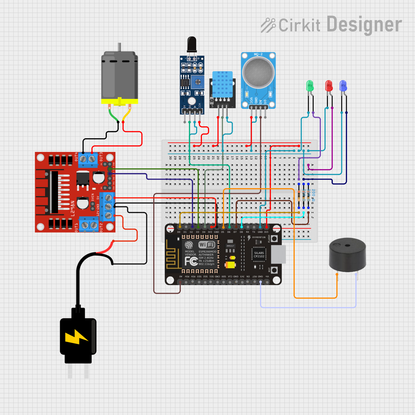
The circuit in question appears to be a multi-sensor system with output indicators and a control unit. It includes temperature and humidity sensing (KY-015 DHT11), gas detection (MQ-2 SENSOR), and flame detection (Sensor SHT113 Flame). The circuit uses an ESP8266 NodeMCU microcontroller for processing sensor data and controlling output devices such as LEDs, a buzzer, and a DC motor through an L298N motor driver. The circuit is powered by a 5V DC source.
Component List
Sensors
- KY-015 DHT11: A combined temperature and humidity sensor.
- Sensor SHT113 Flame: A flame detection sensor with both analog and digital outputs.
- MQ-2 SENSOR: A gas sensor capable of detecting a variety of gases including LPG, smoke, and alcohol.
Output Devices
- LED (Red, Blue, Green): Indicators for various statuses or alerts.
- Buzzer: An audible alert device.
Control and Power
- ESP8266 NodeMCU: A microcontroller with Wi-Fi capabilities for processing and controlling the circuit.
- L298N DC Motor Driver: A driver module for controlling DC motors.
- DC Motor: An electric motor controlled by the L298N driver.
- DC Source 5V: Provides power to the circuit.
Passive Components
- Resistors (200 Ohms): Current-limiting resistors for the LEDs.
Wiring Details
KY-015 DHT11
- 5V: Connected to the 3V3 output of the ESP8266 NodeMCU.
- S: Connected to the D4 pin of the ESP8266 NodeMCU.
- GND: Common ground with other components.
Sensor SHT113 Flame
- A0: Not connected in the provided net list.
- D0: Connected to the D6 pin of the ESP8266 NodeMCU.
- GND: Common ground with other components.
- VCC: Connected to the 3V3 output of the ESP8266 NodeMCU.
MQ-2 SENSOR
- VCC: Connected to the 3V3 output of the ESP8266 NodeMCU.
- GND: Common ground with other components.
- A0: Connected to the A0 pin of the ESP8266 NodeMCU.
- D0: Not connected in the provided net list.
Resistor (200 Ohms)
- pin1: Connected to the anode of the corresponding LED.
- pin2: Connected to a digital pin (D0, D7, or D8) of the ESP8266 NodeMCU.
LED: Two Pin (Red, Blue, Green)
- cathode: Common ground with other components.
- anode: Connected to the corresponding resistor.
Buzzer
- PIN: Connected to the D5 pin of the ESP8266 NodeMCU.
- GND: Common ground with other components.
ESP8266 NodeMCU
- Digital and Analog Pins: Connected to various sensors, LEDs, and the buzzer as detailed above.
- 3V3: Powers the sensors and the L298N motor driver.
- GND: Common ground with other components.
L298N DC Motor Driver
- IN3, IN4: Controlled by the D2 and D3 pins of the ESP8266 NodeMCU respectively.
- 5V: Powered by the 3V3 output of the ESP8266 NodeMCU.
- GND: Common ground with other components.
- 12V: Powered by the VCC of the 5V DC Source.
- OUT3, OUT4: Connected to the pins of the DC Motor.
DC Motor
- pin 1, pin 2: Connected to OUT4 and OUT3 of the L298N motor driver respectively.
DC Source 5V
- VCC: Powers the L298N motor driver.
- GND: Common ground with other components.
Documented Code
No code was provided for the microcontroller. The documentation of the code would typically include descriptions of the functions, algorithms, and logic used to read sensor data, control the output devices, and communicate with other devices or services. Since no code is available, this section cannot be completed. If code becomes available, it should be documented here with comments explaining the purpose and functionality of each section of the code.