
Circuit Documentation
Summary
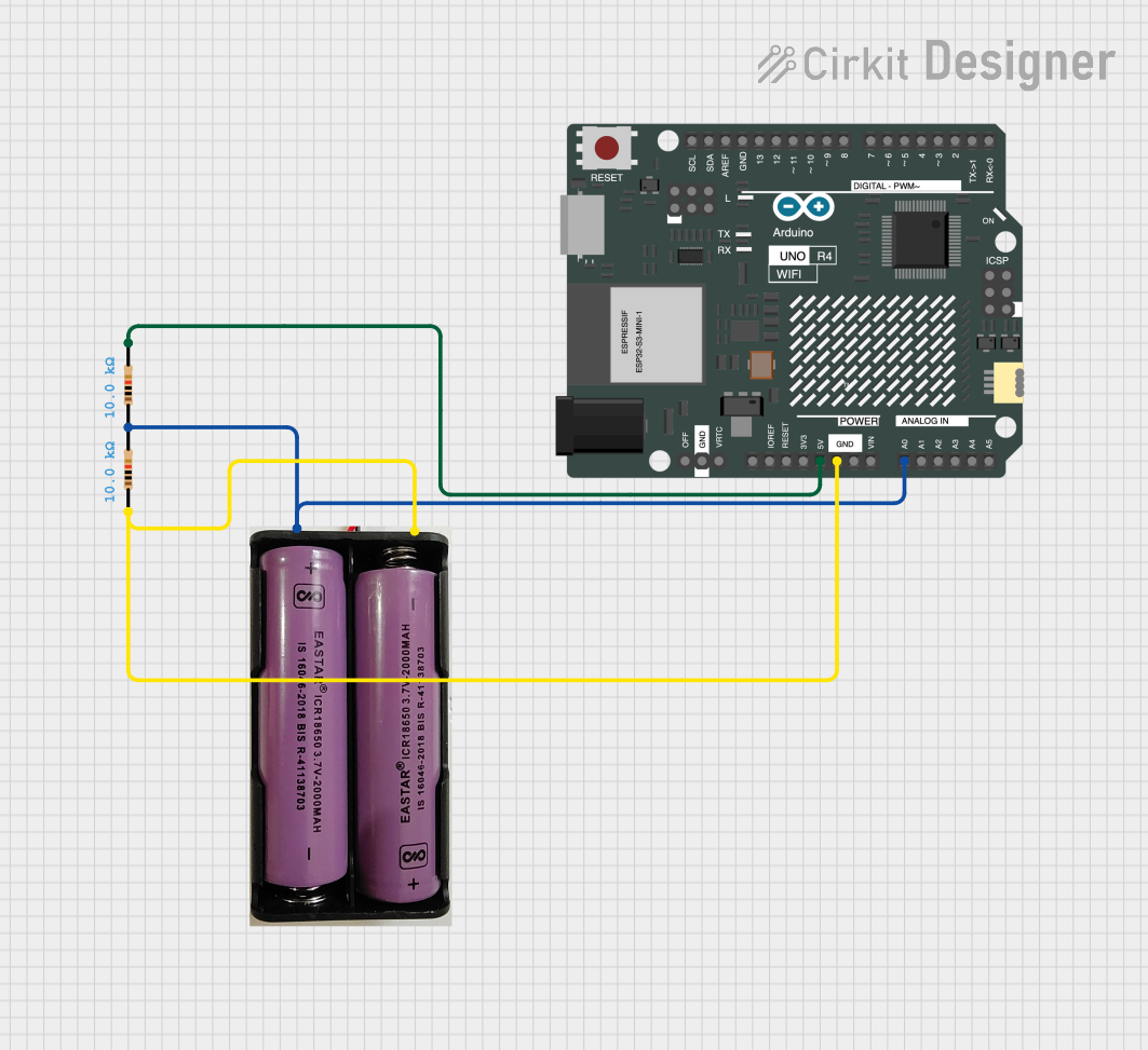
This document provides a detailed overview of a circuit consisting of an Arduino UNO R4 WiFi, two resistors, and a 7.4V power source. The circuit is designed to interface with the Arduino and includes connections to power and ground.
Component List
Arduino UNO R4 WiFi
- Description: A microcontroller board based on the ATmega328P, featuring built-in WiFi capabilities.
- Pins: OFF, GND, VRTC, IIC0_SCL, IIC0_SDA, 3V3, GPIO 41, GPIO 0, GPIO 42, GPIO 43, GPIO 44, BOOT, IOREF, RESET, 5V, VIN, A0, A1, A2, A3, A4, A5, RSPCKA, CIPO, COPI, D0/RX, D1/TX, D2, D3, D4, D5, D6, D7, D8, D9, D10, D11, D12, D13, AREF, SDA, SCL
Resistor 1
- Description: A resistor with a resistance of 10k Ohms.
- Pins: pin1, pin2
- Properties:
- Resistance: 10k Ohms
Resistor 2
- Description: A resistor with a resistance of 10k Ohms.
- Pins: pin1, pin2
- Properties:
- Resistance: 10k Ohms
7.4V Power Source
- Description: A power source providing 7.4V.
- Pins: +, -
Wiring Details
Arduino UNO R4 WiFi
- A0 is connected to pin1 of Resistor 1 and + of 7.4V Power Source.
- 5V is connected to pin2 of Resistor 1.
- GND is connected to pin1 of Resistor 2 and - of 7.4V Power Source.
Resistor 1
- pin1 is connected to A0 of Arduino UNO R4 WiFi and + of 7.4V Power Source.
- pin2 is connected to 5V of Arduino UNO R4 WiFi.
Resistor 2
- pin1 is connected to GND of Arduino UNO R4 WiFi and - of 7.4V Power Source.
- pin2 is not connected.
7.4V Power Source
- + is connected to A0 of Arduino UNO R4 WiFi and pin1 of Resistor 1.
- - is connected to GND of Arduino UNO R4 WiFi and pin1 of Resistor 2.
Documented Code
Arduino UNO R4 WiFi Code
void setup() {
  // put your setup code here, to run once:

}

void loop() {
  // put your main code here, to run repeatedly:

}
Additional Documentation
This document provides a comprehensive overview of the circuit, including a summary, detailed component list, wiring details, and documented code.