
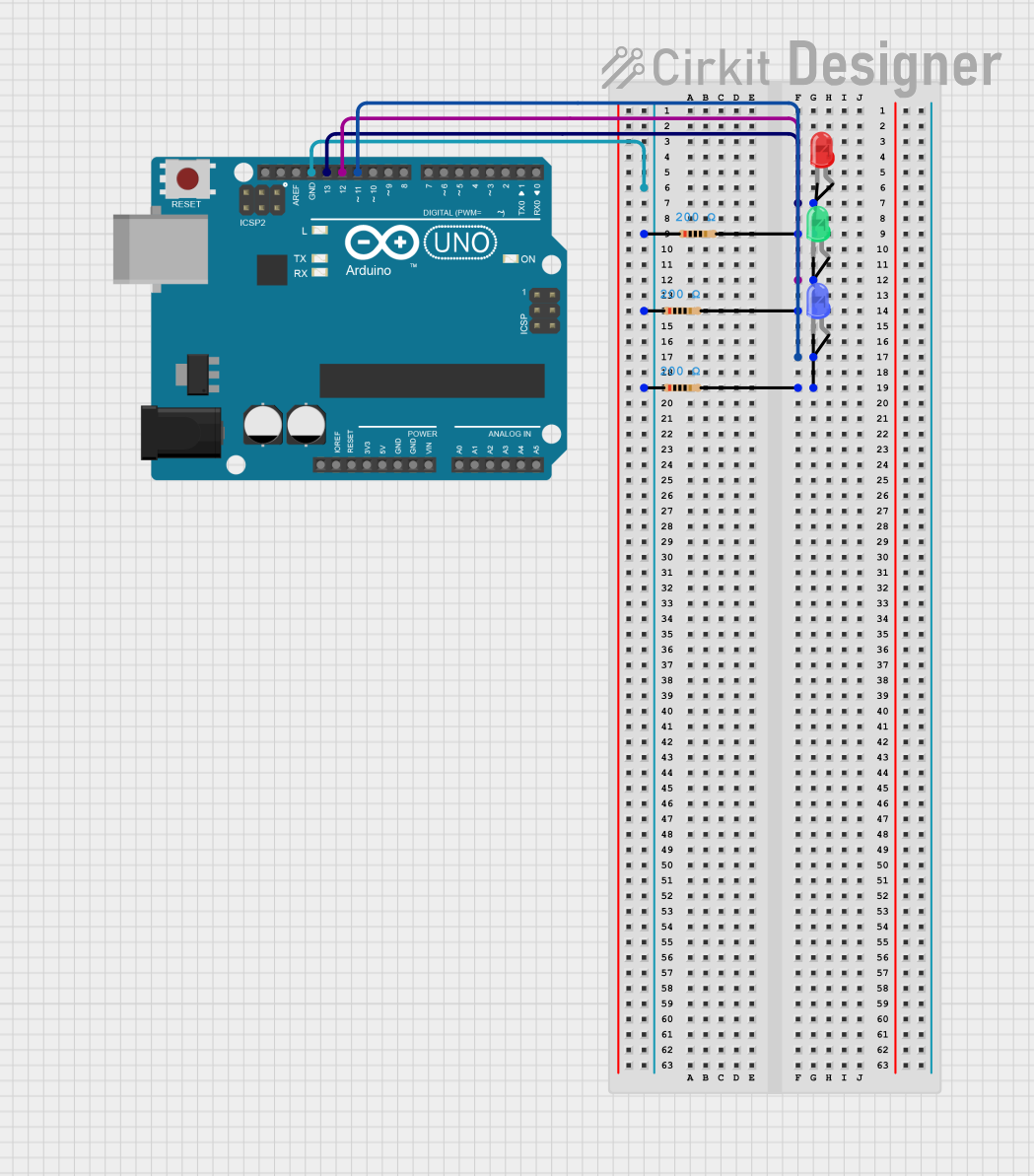
Circuit Documentation
Summary of the Circuit
This circuit is designed to control three LEDs (red, green, and blue) using an Arduino UNO microcontroller. Each LED is connected to a digital output pin on the Arduino (D13 for red, D12 for green, and D11 for blue) and is in series with a 200 Ohm resistor to ground. The purpose of the circuit is to rapidly turn the LEDs on and off in a sequence, creating a blinking effect.
Component List
Arduino UNO
- Description: A microcontroller board based on the ATmega328P.
- Pins Used: D13, D12, D11, GND.
Resistor (200 Ohms)
- Description: A passive two-terminal electrical component that implements electrical resistance as a circuit element.
- Value: 200 Ohms.
LED: Two Pin (red)
- Description: A red light-emitting diode.
- Pins Used: Anode, Cathode.
LED: Two Pin (green)
- Description: A green light-emitting diode.
- Pins Used: Anode, Cathode.
LED: Two Pin (blue)
- Description: A blue light-emitting diode.
- Pins Used: Anode, Cathode.
Wiring Details
Arduino UNO
- D13: Connected to the anode of the red LED.
- D12: Connected to the anode of the green LED.
- D11: Connected to the anode of the blue LED.
- GND: Connected to one pin of each resistor.
Resistor (200 Ohms)
- Pin1: Connected to the GND pin of the Arduino UNO.
- Pin2 (Red LED): Connected to the cathode of the red LED.
- Pin2 (Green LED): Connected to the cathode of the green LED.
- Pin2 (Blue LED): Connected to the cathode of the blue LED.
LED: Two Pin (red)
- Anode: Connected to D13 on the Arduino UNO.
- Cathode: Connected to a 200 Ohm resistor.
LED: Two Pin (green)
- Anode: Connected to D12 on the Arduino UNO.
- Cathode: Connected to a 200 Ohm resistor.
LED: Two Pin (blue)
- Anode: Connected to D11 on the Arduino UNO.
- Cathode: Connected to a 200 Ohm resistor.
Documented Code
/*
 * This Arduino sketch controls three LEDs (red, green, blue) connected to
 * digital pins D13, D12, and D11 respectively. Each LED is connected in
 * series with a 200 Ohm resistor to ground. The sketch will light up the
 * LEDs rapidly in a loop.
 */

// Pin definitions
const int redLEDPin = 13;
const int greenLEDPin = 12;
const int blueLEDPin = 11;

void setup() {
  // Initialize the LED pins as outputs
  pinMode(redLEDPin, OUTPUT);
  pinMode(greenLEDPin, OUTPUT);
  pinMode(blueLEDPin, OUTPUT);
}

void loop() {
  // Turn on all LEDs
  digitalWrite(redLEDPin, HIGH);
  digitalWrite(greenLEDPin, HIGH);
  digitalWrite(blueLEDPin, HIGH);
  delay(100); // Wait for 100 milliseconds

  // Turn off all LEDs
  digitalWrite(redLEDPin, LOW);
  digitalWrite(greenLEDPin, LOW);
  digitalWrite(blueLEDPin, LOW);
  delay(100); // Wait for 100 milliseconds
}
Filename: sketch.ino
This code is designed to run on an Arduino UNO microcontroller. It initializes three digital pins as outputs to control the red, green, and blue LEDs. In the main loop, it turns on all the LEDs for 100 milliseconds, then turns them off for another 100 milliseconds, creating a blinking effect.