
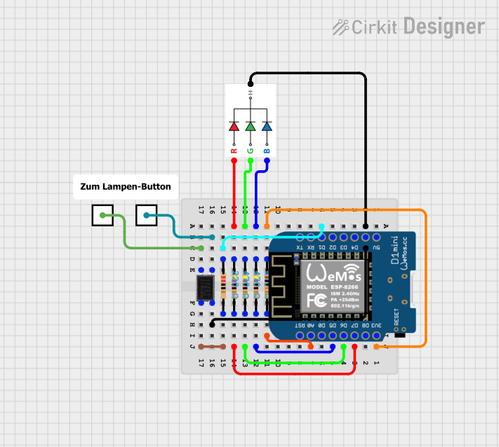
Circuit Documentation
Summary
This circuit is designed to control an "On Air" lamp using a Wemos D1 Mini microcontroller. The lamp features an RGB LED and an optocoupler for external control. The microcontroller connects to a Wi-Fi network and can be controlled via a web server. The RGB LED indicates the status of the lamp, and the optocoupler allows for external signaling.
Component List
RGB LED
- Description: A multi-color LED with Red, Green, and Blue channels.
- Pins: B, G, R, GND
Resistor (100k Ohms)
- Description: Limits current to protect components.
- Pins: pin1, pin2
- Properties: Resistance: 100k Ohms
Resistor (470 Ohms)
- Description: Limits current to protect components.
- Pins: pin1, pin2
- Properties: Resistance: 470 Ohms
Resistor (220 Ohms)
- Description: Limits current to protect components.
- Pins: pin1, pin2
- Properties: Resistance: 220 Ohms
Wemos D1 Mini
- Description: A microcontroller based on the ESP8266, with Wi-Fi capabilities.
- Pins: RST, A0, D0, D5, D6, D7, D8, 3V3, 5V, G, D4, D3, D2, D1, RX, TX
External Connection
- Description: Provides an interface for external connections.
- Pins: External
Octocoupler
- Description: An optocoupler for isolating different sections of the circuit.
- Pins: Anode, Cathode, Collector, Emitter
Wiring Details
RGB LED
- B connected to pin1 of a 470 Ohm Resistor
- G connected to pin1 of a 470 Ohm Resistor
- R connected to pin1 of a 470 Ohm Resistor
- GND connected to G of Wemos D1 Mini and Cathode of Octocoupler
Resistor (100k Ohms)
- pin1 connected to 3V3 of Wemos D1 Mini
- pin2 connected to A0 of Wemos D1 Mini
Resistor (470 Ohms)
pin1 connected to B of RGB LED
pin2 connected to D5 of Wemos D1 Mini
pin1 connected to G of RGB LED
pin2 connected to D6 of Wemos D1 Mini
pin1 connected to R of RGB LED
pin2 connected to D7 of Wemos D1 Mini
Resistor (220 Ohms)
- pin1 connected to D1 of Wemos D1 Mini
- pin2 connected to Anode of Octocoupler
Wemos D1 Mini
- 3V3 connected to pin1 of a 100k Ohm Resistor
- G connected to GND of RGB LED and Cathode of Octocoupler
- D1 connected to pin1 of a 220 Ohm Resistor
- D5 connected to pin2 of a 470 Ohm Resistor
- D6 connected to pin2 of a 470 Ohm Resistor
- D7 connected to pin2 of a 470 Ohm Resistor
- A0 connected to pin2 of a 100k Ohm Resistor
Octocoupler
- Anode connected to pin2 of a 220 Ohm Resistor
- Cathode connected to G of Wemos D1 Mini and GND of RGB LED
- Collector connected to External of External Connection
- Emitter connected to External of External Connection
External Connection
- External connected to Collector of Octocoupler
- External connected to Emitter of Octocoupler
Code Documentation
/*
  On Air Lamp, Version 1.0.0
  Copyright (c) 2024, Heise Medien GmbH & Co. KG / c’t
  Beschreibung des Programms in:
    Hajo Schulz
    Achtung, Aufnahme
    Bastelprojekt: „On Air“-Lampe mit WLAN
    c’t 25/2024, S. 90
    https://www.heise.de/select/ct/archiv/2024/25/seite-090
*/

#include <ESP8266WiFi.h>
#include <WiFiClient.h>
#include <ESP8266WebServer.h>
#include <ESP8266mDNS.h>

// ---
// Configurable settings
// ---
const char* WifiSsid = "Ihre WLAN-SSID";
const char* WifiPwd = "Ihr WLAN-Passwort";
const char* ServerName = "onairlamp";

// ---
// GPIO pins
// ---
// RGB LED on D5 - D7
const int RgbRedPin = D6;
const int RgbGreenPin = D7;
const int RgbBluePin = D5;
// Optocoupler on D1
const int OptoPin = D1;
// LSR on A0;
const int LsrPin = A0;

// ---
// Helpers for RGB LED
// ---
enum RgbColor {
  BLACK  = 0,
  RED    = 1,
  GREEN  = 2,
  YELLOW = 3,
  BLUE   = 4,
  PURPLE = 5,
  CYAN   = 6,
  WHITE  = 7
};

void setRgb(RgbColor color)
{
  digitalWrite(RgbRedPin, color & 1 ? HIGH : LOW);
  digitalWrite(RgbGreenPin, color & 2 ? HIGH : LOW);
  digitalWrite(RgbBluePin, color & 4 ? HIGH : LOW);
}

// ---
// The lamp
// ---
int lampState = 0;
// If you want the lamp to pulsate when "On Air" instead of shining
// continuously, just swap the names of the following two functions.
void lampOn()
{
  digitalWrite(OptoPin, HIGH);
  delay(100);
  digitalWrite(OptoPin, LOW);
  delay(200);
}
void lampOff()
{
  digitalWrite(OptoPin, HIGH);
  delay(100);
  digitalWrite(OptoPin, LOW);
  delay(200);
  digitalWrite(OptoPin, HIGH);
  delay(100);
  digitalWrite(OptoPin, LOW);
  delay(200);
}
void switchLamp(int desiredState = -1)
{
  if(desiredState == -1) {
    desiredState = (lampState == 1 ? 0 : 1);
  }
  if(desiredState != lampState) {
    if(desiredState == 1) {
      lampOn();
    }
    else {
      lampOff();
    }
    lampState = desiredState;
  }
}

// ---
// The web server
// ---
ESP8266WebServer server(80);
bool usingMDNS = false;

String prepareAnswer()
{
  String htmlPage;
  htmlPage.reserve(1024);               // prevent RAM fragmentation
  htmlPage = "<!DOCTYPE HTML>\r\n"
             "<html>\r\n"
             "<head>\r\n"
             "<meta charset=\"utf-8\">\r\n"
             "<title>On-Air-Lampe</title>\r\n"
             "</head>\r\n"
             "<body>\r\n"
             "<h1>On-Air-Lampe</h1>\r\n"
             "<p>Die Lampe ist <span id=\"lampstate\" style=\"font-weight:bold;\">";
  htmlPage += (lampState == 1 ? "an" : "aus");
  htmlPage += "</span>.</p>\r\n"
              "</body></html>\r\n";
  return htmlPage;
}

void handleLamp(int request)
{
  setRgb(YELLOW);
  if(request == 0 || request == 1) {
    switchLamp(request);
  }
  String answer = prepareAnswer();
  server.send(200, "text/html; charset=utf-8", answer.c_str());
  setRgb(GREEN);
}

void handleRoot()
{
  handleLamp(-1);
}

void handleOn()
{
  handleLamp(1);
}

void handleOff()
{
  handleLamp(0);
}

void handleNotFound()
{
  setRgb(RED);
  server.send(404, "text/plain", "404 not found\r\n");
  setRgb(GREEN);
}

// ---
// Initialize everything
// --
void setup(void)
{
  pinMode(RgbRedPin, OUTPUT);
  pinMode(RgbGreenPin, OUTPUT);
  pinMode(RgbBluePin, OUTPUT);
  pinMode(OptoPin, OUTPUT);
  pinMode(LsrPin, INPUT);
  setRgb(BL