
CNC Spindle Control System with VFD and Mach 3 Breakout Board
View and Edit Project In Cirkit Designer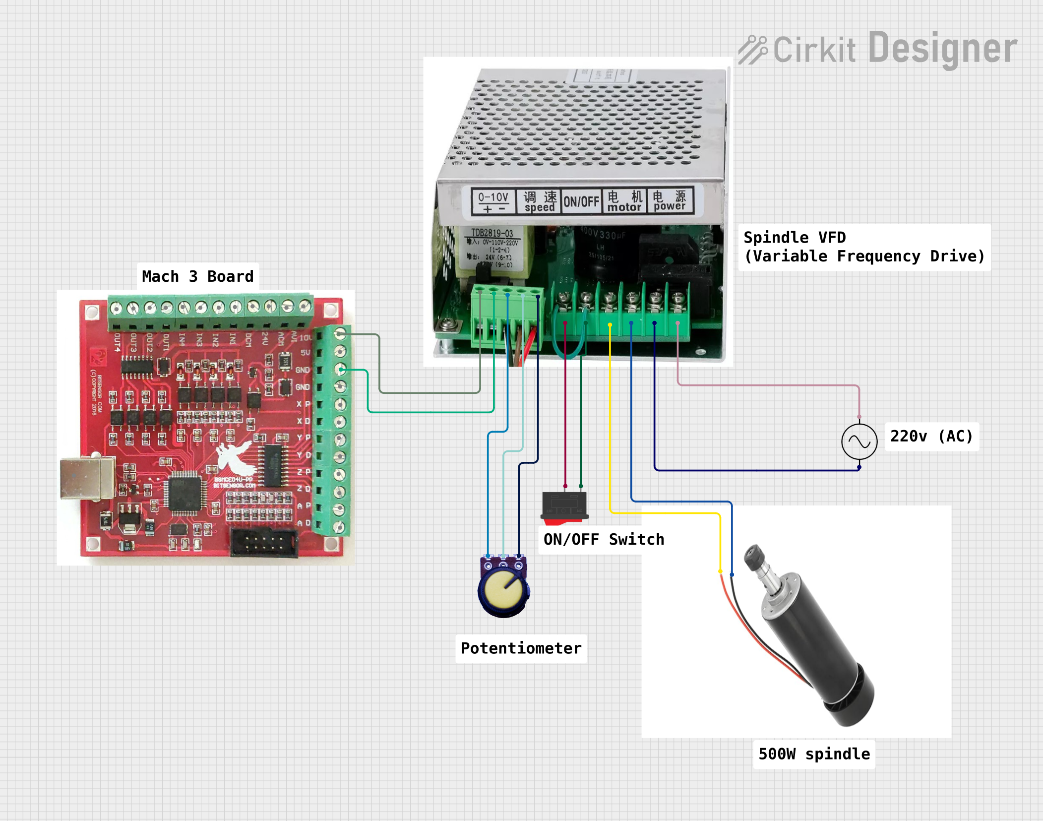
Circuit Documentation
Summary
The circuit in question is designed to control a 500W spindle motor using a CNC Mach 3 Breakout Board and a Variable Frequency Drive (VFD). The VFD is responsible for adjusting the spindle's speed and on/off state, which is modulated by a potentiometer and a rocker switch. The spindle's speed is controlled by a 0-10V signal from the breakout board, and the AC supply provides the necessary power to the VFD, which in turn powers the spindle motor.
Component List
CNC Mach 3 Breakout Board
- Description: A breakout board designed for interfacing with CNC machinery control software, such as Mach 3.
- Pins: AVM, 24V, DCM, IN1-4, OUT1-4, 10V, 5V, GND, XP, XD, YP, YD, ZP, ZD, AP, AD, AVI, CPU.
500W Spindle
- Description: A motor used for CNC machining applications, capable of high-speed rotation.
- Pins: Positive, Negative.
500W Spindle VFD
- Description: A variable frequency drive used to control the speed and on/off state of the spindle motor.
- Pins: 0-10V, GND, Potentiometer GND, Potentiometer output, Potentiometer VCC, ON, OFF, Motor Positive, Motor Negative, +VCC, -VCC.
AC Supply
- Description: Provides the main power source for the VFD.
- Pins: +ve, -ve.
Rocker Switch
- Description: A switch used to toggle the spindle's on/off state.
- Pins: 1, 2.
Potentiometer
- Description: A variable resistor used to adjust the spindle speed by varying the voltage signal to the VFD.
- Pins: GND, Output, VCC.
Comments
- Description: Placeholder components for additional notes or documentation.
Wiring Details
CNC Mach 3 Breakout Board
- 10V pin is connected to the 0-10V pin on the 500W spindle VFD.
500W Spindle
- Positive pin is connected to the Motor Positive pin on the 500W spindle VFD.
- Negative pin is connected to the Motor Negative pin on the 500W spindle VFD.
500W Spindle VFD
- 0-10V pin is connected to the 10V pin on the CNC Mach 3 Breakout Board.
- GND pin is connected to the GND pin on the CNC Mach 3 Breakout Board (not explicitly mentioned in the net list, assumed to be a standard connection).
- Potentiometer GND pin is connected to the VCC pin on the Potentiometer.
- Potentiometer output pin is connected to the Output pin on the Potentiometer.
- Potentiometer VCC pin is connected to the GND pin on the Potentiometer.
- ON pin is connected to the pin 2 on the Rocker Switch.
- OFF pin is connected to the pin 1 on the Rocker Switch.
- Motor Positive pin is connected to the Positive pin on the 500W spindle.
- Motor Negative pin is connected to the Negative pin on the 500W spindle.
- +VCC pin is connected to the +ve pin on the AC Supply.
- -VCC pin is connected to the -ve pin on the AC Supply.
AC Supply
- +ve pin is connected to the +VCC pin on the 500W spindle VFD.
- -ve pin is connected to the -VCC pin on the 500W spindle VFD.
Rocker Switch
- Pin 2 is connected to the ON pin on the 500W spindle VFD.
- Pin 1 is connected to the OFF pin on the 500W spindle VFD.
Potentiometer
- VCC pin is connected to the Potentiometer GND pin on the 500W spindle VFD.
- Output pin is connected to the Potentiometer output pin on the 500W spindle VFD.
- GND pin is connected to the Potentiometer VCC pin on the 500W spindle VFD.
Code Documentation
No code has been provided for any microcontrollers in the circuit. If code is later added for programmable components, such as the CNC Mach 3 Breakout Board, it should be documented in this section with details on functionality, setup, and main loop operations.