Arduino UNO-Based Smart Parking System with LCD Display and IR Sensors
Circuit Documentation
Summary
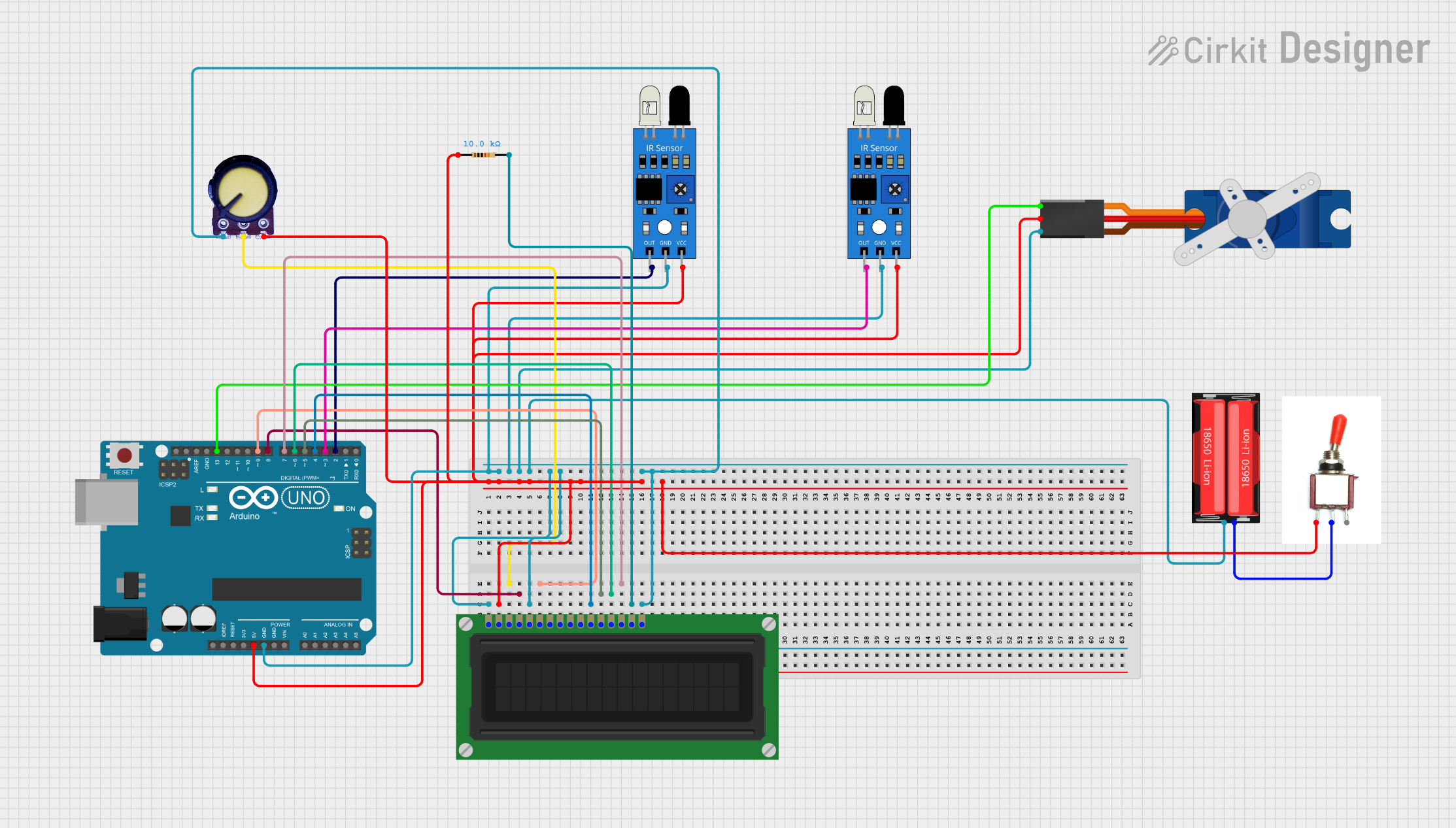
This circuit is designed to manage a parking system using an Arduino UNO microcontroller. The system includes an LCD display for user interface, IR sensors for detecting car entry and exit, a servo motor for gate control, a potentiometer for adjusting the LCD contrast, a toggle switch for power control, and a resistor for current limiting. The system is powered by a 18650 Li-Ion battery.
Component List
LCD Display (16 pin)
- Description: 16x2 character LCD display
- Pins: VSS, VDD, VO, RS, R_W, E, DB0, DB1, DB2, DB3, DB4, DB5, DB6, DB7, A, K
Arduino UNO
- Description: Microcontroller board based on the ATmega328P
- Pins: UNUSED, IOREF, Reset, 3.3V, 5V, GND, Vin, A0, A1, A2, A3, A4, A5, SCL, SDA, AREF, D13, D12, D11, D10, D9, D8, D7, D6, D5, D4, D3, D2, D1, D0
IR Sensor
- Description: Infrared sensor for detecting objects
- Pins: out, gnd, vcc
Potentiometer
- Description: Variable resistor for adjusting voltage
- Pins: GND, Output, VCC
Tower Pro SG90 Servo
- Description: Small servo motor for precise control
- Pins: Signal, +5V, GND
18650 Li-Ion Battery
- Description: Rechargeable lithium-ion battery
- Pins: Positive, Negative
Resistor
- Description: 10k Ohm resistor for current limiting
- Pins: pin1, pin2
Toggle Switch
- Description: Switch for controlling power
- Pins: Vcc, Sig, Gnd
Wiring Details
LCD Display (16 pin)
- VSS: Connected to GND
- VDD: Connected to 5V
- VO: Connected to Potentiometer Output
- RS: Connected to Arduino UNO D8
- R_W: Connected to GND
- E: Connected to Arduino UNO D9
- DB4: Connected to Arduino UNO D4
- DB5: Connected to Arduino UNO D5
- DB6: Connected to Arduino UNO D6
- DB7: Connected to Arduino UNO D7
- A: Connected to Resistor pin2
- K: Connected to GND
Arduino UNO
- 5V: Connected to VDD of LCD Display, vcc of IR Sensors, +5V of Servo, VCC of Potentiometer, Vcc of Toggle Switch
- GND: Connected to GND of LCD Display, gnd of IR Sensors, GND of Servo, GND of Potentiometer, Negative of 18650 Li-Ion Battery
- D8: Connected to RS of LCD Display
- D9: Connected to E of LCD Display
- D4: Connected to DB4 of LCD Display
- D5: Connected to DB5 of LCD Display
- D6: Connected to DB6 of LCD Display
- D7: Connected to DB7 of LCD Display
- D13: Connected to Signal of Servo
- D3: Connected to out of IR Sensor (exit)
- D2: Connected to out of IR Sensor (entry)
IR Sensor (entry)
- out: Connected to Arduino UNO D2
- gnd: Connected to GND
- vcc: Connected to 5V
IR Sensor (exit)
- out: Connected to Arduino UNO D3
- gnd: Connected to GND
- vcc: Connected to 5V
Potentiometer
- GND: Connected to GND
- Output: Connected to VO of LCD Display
- VCC: Connected to 5V
Tower Pro SG90 Servo
- Signal: Connected to Arduino UNO D13
- +5V: Connected to 5V
- GND: Connected to GND
18650 Li-Ion Battery
- Positive: Connected to Sig of Toggle Switch
- Negative: Connected to GND
Resistor
- pin1: Connected to 5V
- pin2: Connected to A of LCD Display
Toggle Switch
- Vcc: Connected to 5V
- Sig: Connected to Positive of 18650 Li-Ion Battery
- Gnd: Connected to GND
Code Documentation
#include <LiquidCrystal.h>  // Include the standard LiquidCrystal library
#include <Servo.h>

Servo myservo1;

int IR1 = 2;  // IR sensor for parking entry
int IR2 = 3;  // IR sensor for parking exit

int Slot = 4;  // Total number of parking slots

int flag1 = 0;
int flag2 = 0;

// Define the pins for the LCD (RS, E, D4, D5, D6, D7)
LiquidCrystal lcd(8, 9, 4, 5, 6, 7);  // Adjust the pin numbers to match your wiring

void setup() {
  lcd.begin(16, 2);  // Initialize the LCD with 16 columns and 2 rows
  lcd.backlight();  // Turn on the backlight

  pinMode(IR1, INPUT);  // Set IR1 as input
  pinMode(IR2, INPUT);  // Set IR2 as input

  myservo1.attach(13);  // Attach the servo to pin 6
  myservo1.write(100); // Initial position (closed)

  lcd.setCursor(0, 0);
  lcd.print("     ARDUINO    ");
  lcd.setCursor(0, 1);
  lcd.print(" PARKING SYSTEM ");
  delay(2000);
  lcd.clear();
}

void loop() {

  // Check if car enters the parking lot (IR1 sensor triggered)
  if(digitalRead(IR1) == LOW && flag1 == 0) {
    if(Slot > 0) {
      flag1 = 1;
      if(flag2 == 0) {
        myservo1.write(0); // Open the gate
        Slot = Slot - 1;   // Decrease the available slots
      }
    } else {
      lcd.setCursor(0, 0);
      lcd.print("    SORRY :(    ");
      lcd.setCursor(0, 1);
      lcd.print("  Parking Full  ");
      delay(3000);
      lcd.clear();
    }
  }

  // Check if car leaves the parking lot (IR2 sensor triggered)
  if(digitalRead(IR2) == LOW && flag2 == 0) {
    flag2 = 1;
    if(flag1 == 0) {
      myservo1.write(0);  // Open the gate
      Slot = Slot + 1;    // Increase the available slots
    }
  }

  // Close the gate after both entry and exit actions are completed
  if(flag1 == 1 && flag2 == 1) {
    delay(1000);          // Wait for a moment before closing the gate
    myservo1.write(100); // Close the gate
    flag1 = 0;           // Reset flags
    flag2 = 0;
  }

  // Display the available parking slots on the LCD
  lcd.setCursor(0, 0);
  lcd.print("    WELCOME!    ");
  lcd.setCursor(0, 1);
  lcd.print("Slot Left: ");
  lcd.print(Slot);
}
This code initializes the LCD display and servo motor, sets up the IR sensors, and manages the parking slots. The LCD displays a welcome message and the number of available slots. The servo motor controls the gate, opening it when a car enters or exits, and closing it after the action is completed. The IR sensors detect the presence of cars at the entry and exit points.