
Circuit Documentation
Summary of the Circuit
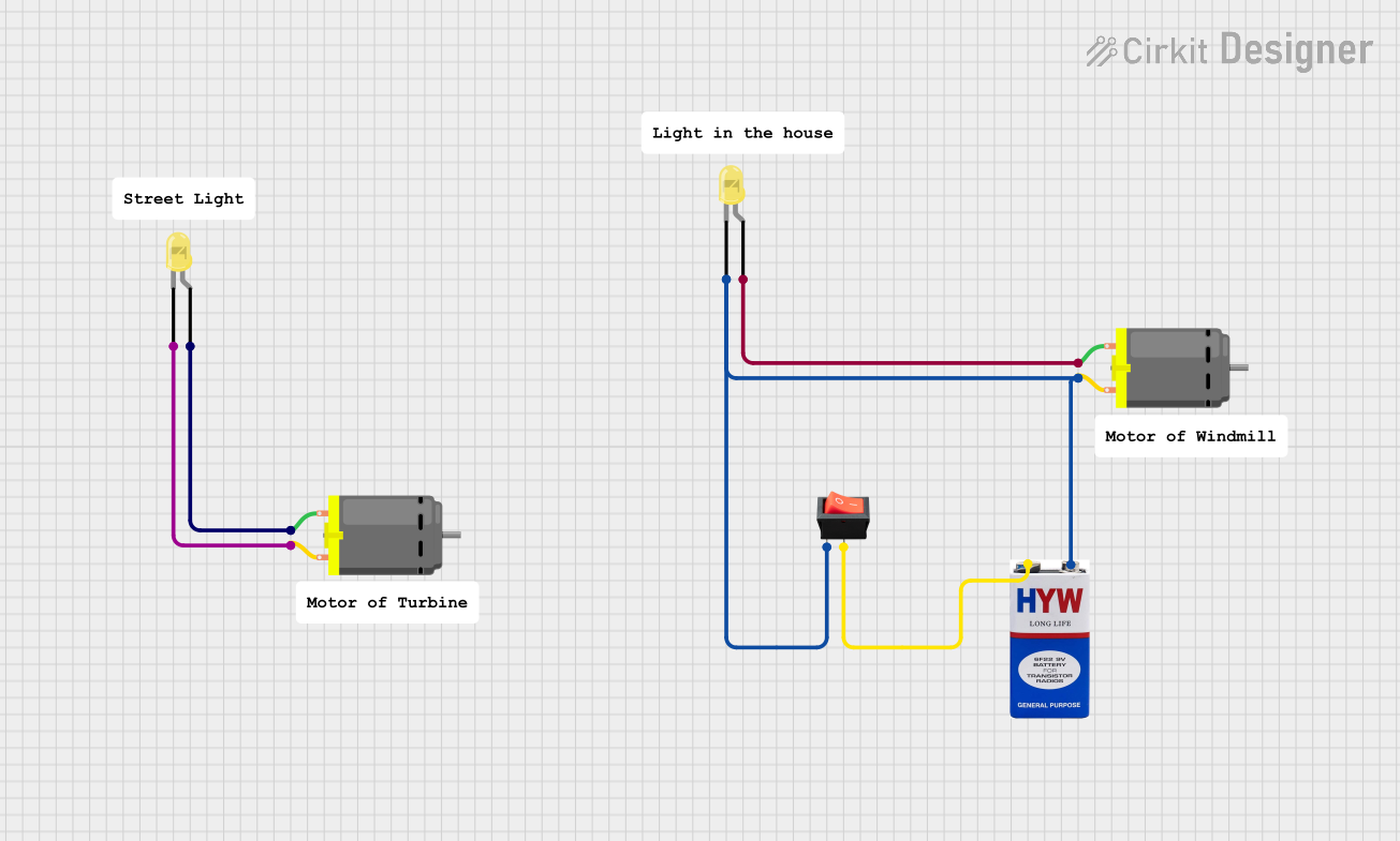
The circuit described by the provided inputs consists of a simple control and power system that includes two DC motors, two yellow LEDs, a rocker switch, and a 9V battery. The circuit appears to be designed to control the operation of the DC motors and LEDs using the rocker switch. When the switch is turned on, it likely allows current to flow from the battery to the motors and LEDs, causing the motors to spin and the LEDs to light up. The absence of a microcontroller and associated code indicates that the circuit functions purely through direct electrical connections without any programmable control logic.
Component List
LED: Two Pin (yellow)
- Description: A yellow light-emitting diode with two pins: an anode and a cathode.
- Purpose: To provide visual indication when powered.
DC Motor
- Description: An electric motor that runs on direct current (DC) electricity.
- Purpose: To convert electrical energy into mechanical motion.
Rocker Switch
- Description: A switch that rocks back and forth when pressed, with one side being raised and the other depressed.
- Purpose: To control the flow of electricity in the circuit, acting as an on/off switch.
9V Battery
- Description: A standard 9-volt battery with a positive and a negative terminal.
- Purpose: To provide the power source for the circuit.
Comment
- Description: A placeholder for additional information or notes within the circuit diagram.
- Purpose: To provide context or explanations as needed (not an electrical component).
Wiring Details for Each Component
LED: Two Pin (yellow)
- Cathode is connected to:
- The negative terminal of the 9V battery (common ground net).
- Pin 2 of one of the DC Motors.
- Anode is connected to:
- Pin 1 of the same DC Motor.
DC Motor
Pin 1 of the first DC Motor is connected to:
- The anode of one of the yellow LEDs.
Pin 2 of the first DC Motor is connected to:
- The cathode of the same yellow LED.
Pin 1 of the second DC Motor is connected to:
- The anode of the second yellow LED.
Pin 2 of the second DC Motor is connected to:
- The negative terminal of the 9V battery (common ground net).
- The input pin of the rocker switch.
- The cathode of the second yellow LED.
Rocker Switch
- Input is connected to:
- The negative terminal of the 9V battery (common ground net).
- Pin 2 of the second DC Motor.
- The cathode of the second yellow LED.
- Output is connected to:
- The positive terminal of the 9V battery.
9V Battery
- Positive (+) terminal is connected to:
- The output pin of the rocker switch.
- Negative (-) terminal is connected to:
- The cathode of the first yellow LED.
- Pin 2 of the first DC Motor.
- The cathode of the second yellow LED.
- Pin 2 of the second DC Motor.
- The input pin of the rocker switch.
Documented Code
No code has been provided for this circuit as there are no programmable components such as microcontrollers included in the design. The circuit operates purely on the basis of the electrical connections and the mechanical action of the rocker switch.