Cirkit Designer
Your all-in-one circuit design IDE
Home /
Project Documentation
Arduino-Controlled Robotics Platform with Dual L298N Motor Drivers and QMC5883L Magnetometer
Circuit Documentation
Summary
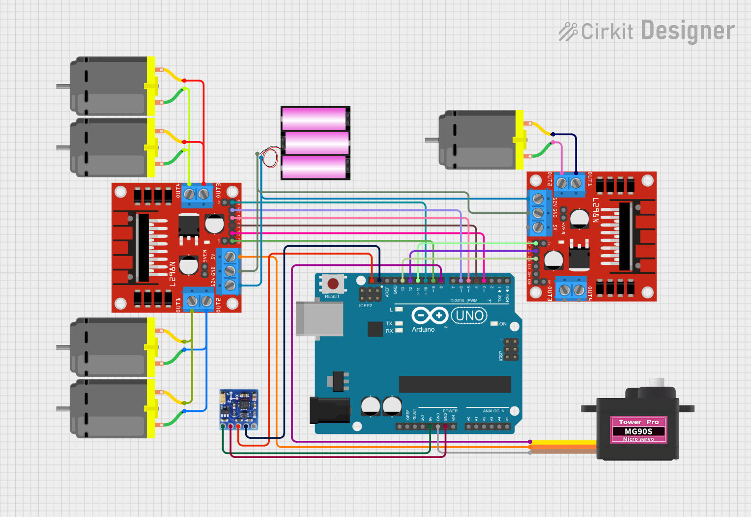
This circuit is designed to control multiple DC motors and a servomotor, with the capability to read data from a QMC5883L magnetometer. The control logic is managed by an Arduino UNO microcontroller, which interfaces with the motors through L298N DC motor drivers. The servomotor is directly controlled by the Arduino UNO. The magnetometer is connected to the Arduino's I2C bus for communication. A 12V battery provides power to the motor drivers and indirectly to the servomotor.
Component List
Arduino UNO
- Microcontroller board based on the ATmega328P
- Provides GPIO pins for interfacing with other components
- Has onboard voltage regulation and can be powered via USB or an external power supply
L298N DC Motor Driver (x2)
- Dual H-bridge motor driver capable of driving two DC motors each
- Supports motors that require up to 2A of current
- Provides pins for motor control inputs and motor power outputs
DC Motor (x5)
- Standard DC motors for rotational motion
- Requires two connections for power and ground
Battery 12V
- Provides the main power source for the motor drivers
- Has a positive (+) and negative (-) terminal
Servomotor MG90S
- A small and lightweight servomotor for precise angular positioning
- Has three connections: signal (SIG), power (VCC), and ground (GND)
QMC5883L Magnetometer
- A digital compass sensor for detecting magnetic fields
- Communicates with the Arduino UNO via the I2C bus
Wiring Details
Arduino UNO
5Vconnected to QMC5883L MagnetometerVCCGNDconnected to Servomotor MG90SGNDand QMC5883L MagnetometerGNDSCLconnected to QMC5883L MagnetometerSCLSDAconnected to QMC5883L MagnetometerSDA- Digital pins
D13,D12,D11,D10,D9,D8,D6,D5,D4,D3connected to correspondingINandENpins on L298N DC motor drivers D8connected to Servomotor MG90SSIG
L298N DC Motor Driver
12Vconnected to the positive terminal of the 12V batteryGNDconnected to the negative terminal of the 12V battery5V(from one driver) connected to Servomotor MG90SVCC- Motor control inputs (
IN1,IN2,IN3,IN4,ENA,ENB) connected to corresponding Arduino UNO digital pins - Motor power outputs (
OUT1,OUT2,OUT3,OUT4) connected to DC Motor pins
DC Motors
- Each motor has two pins (
pin 1,pin 2) connected to the corresponding outputs on the L298N DC motor drivers
Battery 12V
+connected to12Von both L298N DC motor drivers-connected toGNDon both L298N DC motor drivers
Servomotor MG90S
VCCconnected to5Von one of the L298N DC motor driversGNDconnected to Arduino UNOGNDSIGconnected to Arduino UNOD8
QMC5883L Magnetometer
VCCconnected to Arduino UNO5VGNDconnected to Arduino UNOGNDSCLconnected to Arduino UNOSCLSDAconnected to Arduino UNOSDA
Documented Code
Arduino UNO Code (sketch.ino)
void setup() {
  // put your setup code here, to run once:

}

void loop() {
  // put your main code here, to run repeatedly:

}
Note: The provided code is a template and does not contain any functional logic. It needs to be populated with the specific control code for the motors and the magnetometer.