
Arduino Nano-Based Smart Power Monitoring System with LCD Display
View and Edit Project In Cirkit Designer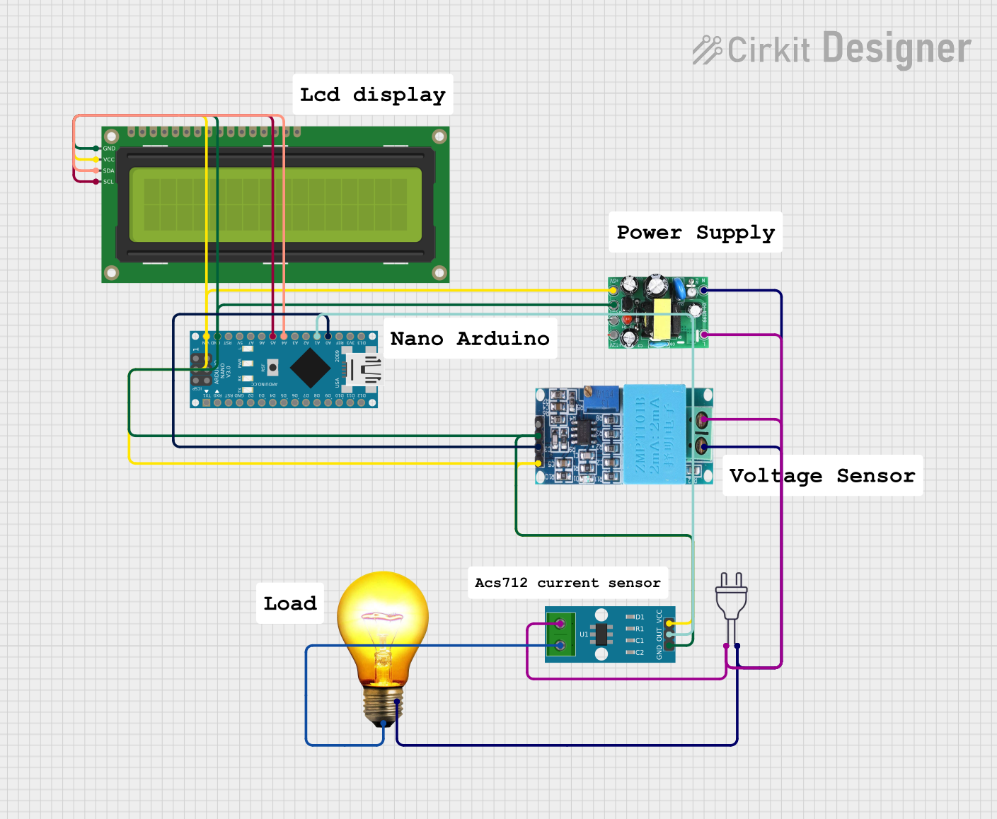
Circuit Documentation
Summary
This circuit involves an Arduino Nano microcontroller interfaced with a ZMPT101B voltage sensor, an ACS712 current sensor, and a 16x2 I2C LCD display. The circuit is designed to measure voltage and current, and display the readings on the LCD. Additionally, an AC bulb is included in the circuit to demonstrate the load.
Component List
ZMPT101B Voltage Sensor
- Description: Measures AC voltage.
- Pins: OUT, GND, VCC, NEUTRO, FASE
Arduino Nano
- Description: Microcontroller board based on the ATmega328P.
- Pins: D1/TX, D0/RX, RESET, GND, D2, D3, D4, D5, D6, D7, D8, D9, D10, D11/MOSI, D12/MISO, VIN, 5V, A7, A6, A5, A4, A3, A2, A1, A0, AREF, 3V3, D13/SCK
16x2 I2C LCD
- Description: 16x2 character LCD display with I2C interface.
- Pins: GND, VCC, SDA, SCL
ACS712 Current Sensor 5A 20A 30A
- Description: Measures AC and DC current.
- Pins: 1, 2, GND, OUT, VCC
AC Bulb
- Description: Standard AC bulb used as a load.
- Pins: P, N
AC to DC Converter
- Description: Converts AC voltage to DC voltage.
- Pins: 12v, -, 5v, live, neutral
Power 220V
- Description: Provides 220V AC power.
- Pins: hot wire, neutral wire
Wiring Details
ZMPT101B Voltage Sensor
- OUT connected to A0 of Arduino Nano
- GND connected to GND of Arduino Nano, 16x2 I2C LCD, ACS712 Current Sensor, and AC to DC Converter
- VCC connected to VIN of Arduino Nano, VCC of 16x2 I2C LCD, VCC of ACS712 Current Sensor, and 5v of AC to DC Converter
- NEUTRO connected to N of AC Bulb, neutral wire of Power 220V, and neutral of AC to DC Converter
- FASE connected to hot wire of Power 220V, 1 of ACS712 Current Sensor, and live of AC to DC Converter
Arduino Nano
- A0 connected to OUT of ZMPT101B Voltage Sensor
- GND connected to GND of ZMPT101B Voltage Sensor, 16x2 I2C LCD, ACS712 Current Sensor, and AC to DC Converter
- VIN connected to VCC of ZMPT101B Voltage Sensor, 16x2 I2C LCD, ACS712 Current Sensor, and 5v of AC to DC Converter
- A5 connected to SCL of 16x2 I2C LCD
- A4 connected to SDA of 16x2 I2C LCD
- A1 connected to OUT of ACS712 Current Sensor
16x2 I2C LCD
- GND connected to GND of Arduino Nano, ZMPT101B Voltage Sensor, ACS712 Current Sensor, and AC to DC Converter
- VCC connected to VIN of Arduino Nano, VCC of ZMPT101B Voltage Sensor, ACS712 Current Sensor, and 5v of AC to DC Converter
- SCL connected to A5 of Arduino Nano
- SDA connected to A4 of Arduino Nano
ACS712 Current Sensor
- 1 connected to FASE of ZMPT101B Voltage Sensor, hot wire of Power 220V, and live of AC to DC Converter
- 2 connected to P of AC Bulb
- GND connected to GND of Arduino Nano, ZMPT101B Voltage Sensor, 16x2 I2C LCD, and AC to DC Converter
- OUT connected to A1 of Arduino Nano
- VCC connected to VIN of Arduino Nano, VCC of ZMPT101B Voltage Sensor, 16x2 I2C LCD, and 5v of AC to DC Converter
AC Bulb
- P connected to 2 of ACS712 Current Sensor
- N connected to NEUTRO of ZMPT101B Voltage Sensor, neutral wire of Power 220V, and neutral of AC to DC Converter
AC to DC Converter
- 12v not connected
- - connected to GND of Arduino Nano, ZMPT101B Voltage Sensor, 16x2 I2C LCD, and ACS712 Current Sensor
- 5v connected to VIN of Arduino Nano, VCC of ZMPT101B Voltage Sensor, 16x2 I2C LCD, and ACS712 Current Sensor
- live connected to FASE of ZMPT101B Voltage Sensor, hot wire of Power 220V, and 1 of ACS712 Current Sensor
- neutral connected to NEUTRO of ZMPT101B Voltage Sensor, N of AC Bulb, and neutral wire of Power 220V
Power 220V
- hot wire connected to FASE of ZMPT101B Voltage Sensor, 1 of ACS712 Current Sensor, and live of AC to DC Converter
- neutral wire connected to NEUTRO of ZMPT101B Voltage Sensor, N of AC Bulb, and neutral of AC to DC Converter
Documented Code
Arduino Nano Code (sketch.ino)
void setup() {
  // put your setup code here, to run once:

}

void loop() {
  // put your main code here, to run repeatedly:

}
Additional Documentation (documentation.txt)