Battery-Powered Buzzer Alarm with Limit Switch
Circuit Documentation
Summary of the Circuit
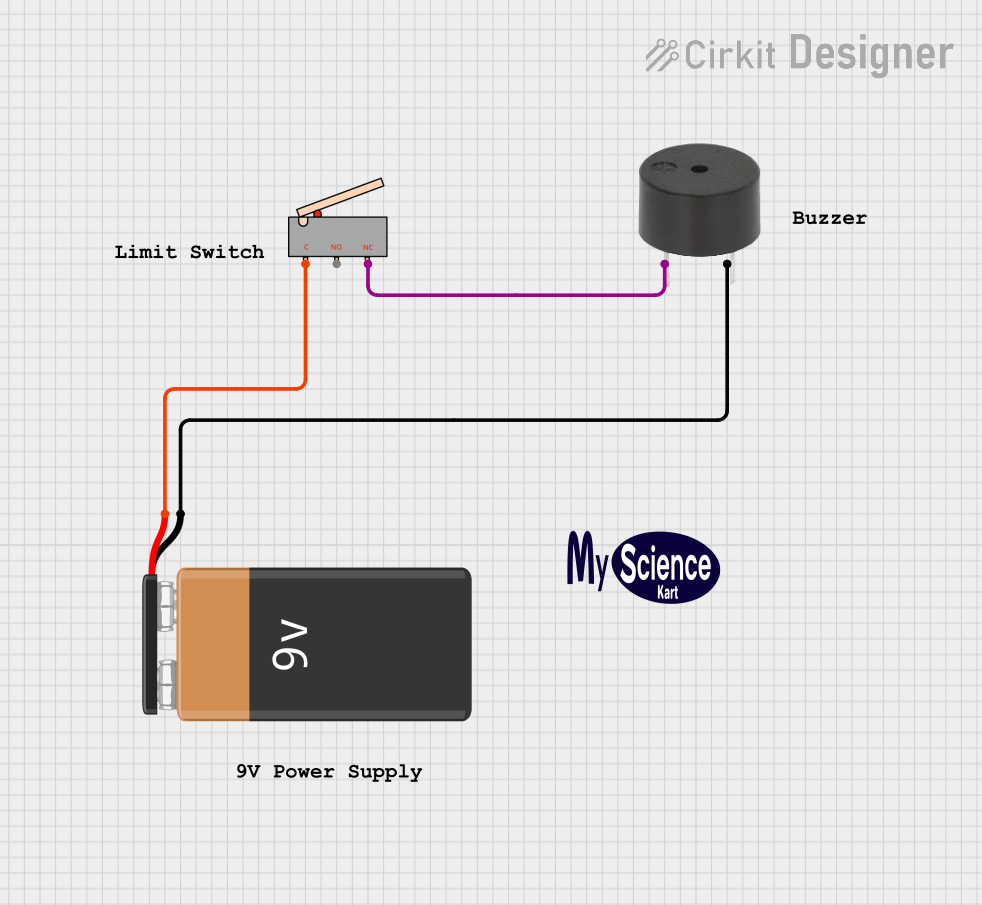
The circuit described by the provided inputs consists of a simple control mechanism using a limit switch to activate a buzzer when a certain condition is met, powered by a 9V battery. The limit switch has three terminals: common (C), normally open (NO), and normally closed (NC). In this circuit, the common terminal is connected to the positive terminal of the battery, and the normally closed terminal is connected to the buzzer. The buzzer has two terminals: one for the signal input (PIN) and one for the ground (GND). The ground terminal of the buzzer is connected to the negative terminal of the battery. This setup ensures that the buzzer is activated when the limit switch is in its default position (NC contact is closed).
Component List
Limit Switch
- Pins: C, NO, NC
- Description: A limit switch is an electromechanical device that consists of an actuator mechanically linked to a set of contacts. When an object comes into contact with the actuator, the device operates the contacts to make or break an electrical connection.
- Purpose in Circuit: The limit switch in this circuit is used to control the activation of the buzzer based on the position of the switch's actuator.
Buzzer
- Pins: PIN, GND
- Description: A buzzer is an audio signaling device, which may be mechanical, electromechanical, or piezoelectric.
- Purpose in Circuit: The buzzer emits a sound when it is electrically powered, serving as an audible indicator when the limit switch is triggered.
9V Battery
- Pins: -, +
- Description: A 9V battery is a common power source for small electronic devices and circuits.
- Purpose in Circuit: The battery provides the necessary power to the circuit, allowing the buzzer to function when the limit switch is activated.
Logo
- Pins: N/A
- Description: Typically, a logo represents branding or identification for the circuit but does not have an electrical function.
- Purpose in Circuit: The logo is likely used for identification or branding purposes and does not contribute to the circuit's functionality.
Comments
- Pins: N/A
- Description: Comments are non-functional elements that can provide additional information or instructions regarding the circuit.
- Purpose in Circuit: Comments may contain notes or explanations but do not have an electrical role in the circuit.
Wiring Details
Limit Switch
- Common (C): Connected to the positive (+) terminal of the 9V Battery.
- Normally Closed (NC): Connected to the PIN terminal of the buzzer.
Buzzer
- PIN: Connected to the Normally Closed (NC) terminal of the Limit Switch.
- GND: Connected to the negative (-) terminal of the 9V Battery.
9V Battery
- Positive (+): Connected to the Common (C) terminal of the Limit Switch.
- Negative (-): Connected to the GND terminal of the buzzer.
Documented Code
There is no embedded code provided for any microcontrollers in this circuit. Therefore, this section is not applicable to the current documentation.