
Arduino UNO-Based Smart Home Automation with Servo, LED Strip, and Fan Control
View and Edit Project In Cirkit Designer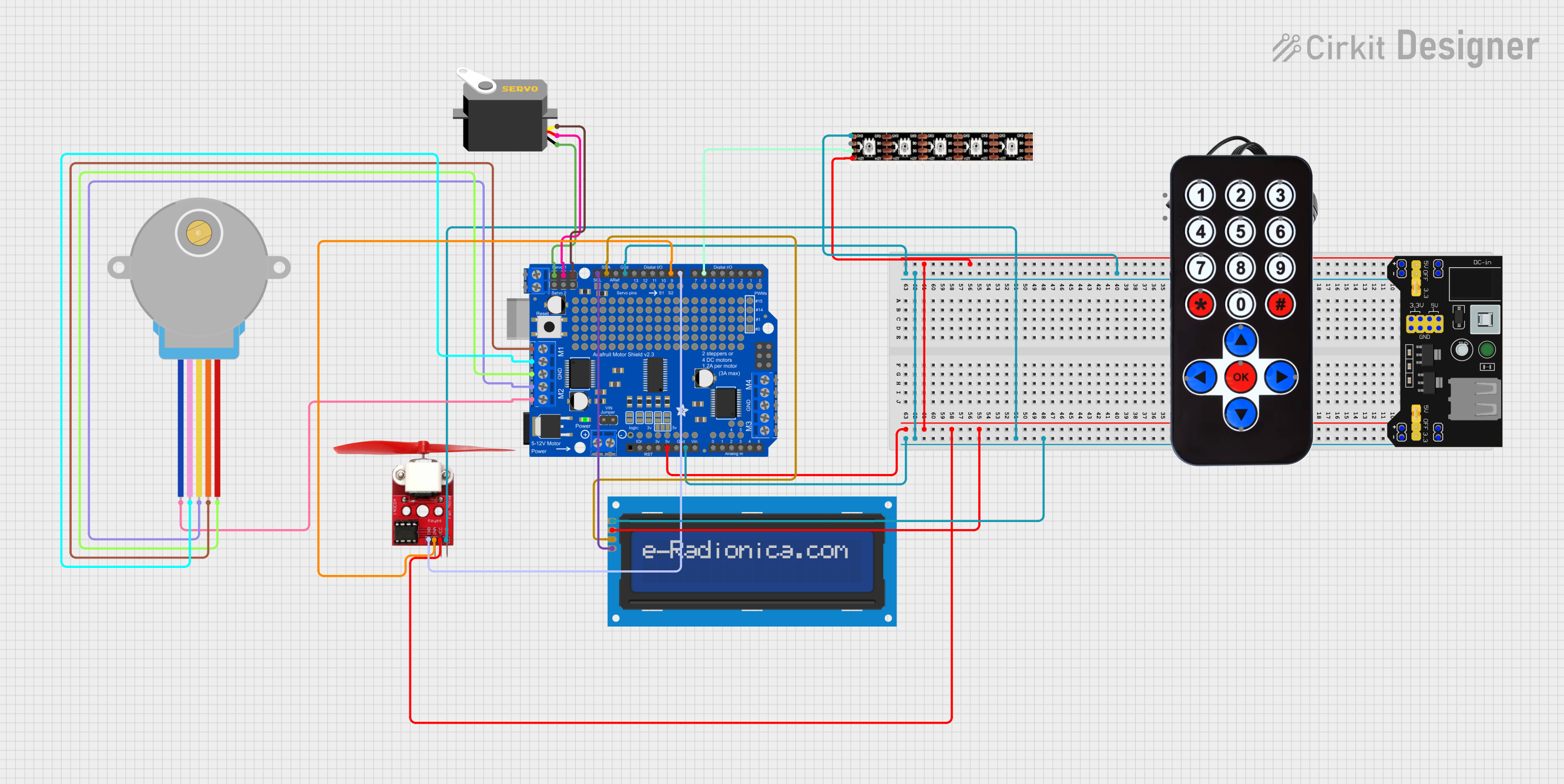
Circuit Documentation
Summary
This circuit integrates various components including a servo motor, an LED strip, a stepper motor, a fan motor, an LCD screen, an IR receiver, and an Arduino UNO microcontroller. The circuit is designed to control these components using the Arduino UNO, which is programmed to manage the operations of the servo, LED strip, fan motor, and other peripherals.
Component List
Servo
- Description: A motor that can be positioned to specific angles.
- Pins: gnd, vcc, pulse
WS2815 LED Strip
- Description: An addressable LED strip that can display various colors.
- Pins: GND, B0, D0, +12V
Arduino UNO
- Description: A microcontroller board based on the ATmega328P.
- Pins: UNUSED, IOREF, Reset, 3.3V, 5V, GND, Vin, A0, A1, A2, A3, A4, A5, SCL, SDA, AREF, D13, D12, D11, D10, D9, D8, D7, D6, D5, D4, D3, D2, D1, D0
28BYJ-48 Stepper Motor
- Description: A small stepper motor used for precise control of rotation.
- Pins: BLUE, PINK, YELLOW, ORANGE, RED
Adafruit Motor, Stepper & Servo Shield
- Description: A shield for Arduino that allows control of motors, steppers, and servos.
- Pins: AD3, AD2, AD1, AD0, D0, D1, D2, D3, D4, D5, D6, D7, PWM0, PWM1, PWM14, PWM15, VIN, GND, +5V, +3V3, /RST, IOREF, AD5/SCL, AD4/SDA, AREF, D13, D12, D11, D10, D9, D8, MISO, MOSI, SCK, M1A, M1B, M2B, M2A, M3A, M3B, M4B, M4A, VMOTOR
LCD screen 16x2 I2C
- Description: A 16x2 character LCD screen with I2C interface.
- Pins: SCL, SDA, VCC, GND
fan motor L9110
- Description: A small DC fan motor.
- Pins: INB, INA, VCC, GND
MB102 Breadboard Power Supply Module 3.3V/5V
- Description: A power supply module for breadboards, providing 3.3V and 5V outputs.
- Pins: VCC, GND, 3.3V, 5V
12v power supply
- Description: A power supply providing 12V output.
- Pins: +, -
IR Receiver
- Description: An infrared receiver for remote control signals.
- Pins: DATA, VCC, GND
HX1838 Infared IR Wireless Remote Control
- Description: An infrared remote control.
- Pins: FFA25D (1), FF629D (2), FFE21D (3), FF22DD (4), FF02FD (5), FFC23D (6), FFE01F (7), FFA857 (8), FF906F (9), FF9867 (0), FFB04F (#), FF6897 (*), FF18E7 (↑), FF5AA5 (→), FF10EF (←), FF4AB5 (↓), FF38C7 (OK)
Wiring Details
Servo
- gnd connected to Adafruit Motor, Stepper & Servo Shield GND
- vcc connected to Adafruit Motor, Stepper & Servo Shield +5V
- pulse connected to Adafruit Motor, Stepper & Servo Shield D10
WS2815 LED Strip
- GND connected to MB102 Breadboard Power Supply Module 3.3V/5V GND
- D0 connected to Arduino UNO D6
- +12V connected to MB102 Breadboard Power Supply Module 3.3V/5V VCC
Arduino UNO
- GND connected to MB102 Breadboard Power Supply Module 3.3V/5V GND
- 5V connected to MB102 Breadboard Power Supply Module 3.3V/5V VCC
- SCL connected to LCD screen 16x2 I2C SCL
- SDA connected to LCD screen 16x2 I2C SDA
- D8 connected to fan motor L9110 INB
- D6 connected to WS2815 LED Strip D0
28BYJ-48 Stepper Motor
- BLUE connected to Adafruit Motor, Stepper & Servo Shield M2A
- PINK connected to Adafruit Motor, Stepper & Servo Shield M1B
- YELLOW connected to Adafruit Motor, Stepper & Servo Shield M2B
- ORANGE connected to Adafruit Motor, Stepper & Servo Shield M1A
- RED connected to Adafruit Motor, Stepper & Servo Shield GND
Adafruit Motor, Stepper & Servo Shield
- GND connected to Servo gnd
- +5V connected to Servo vcc
- D10 connected to Servo pulse
- D9 connected to fan motor L9110 INA
LCD screen 16x2 I2C
- SCL connected to Arduino UNO SCL
- SDA connected to Arduino UNO SDA
- VCC connected to MB102 Breadboard Power Supply Module 3.3V/5V VCC
- GND connected to MB102 Breadboard Power Supply Module 3.3V/5V GND
fan motor L9110
- INB connected to Arduino UNO D8
- INA connected to Adafruit Motor, Stepper & Servo Shield D9
- VCC connected to MB102 Breadboard Power Supply Module 3.3V/5V VCC
- GND connected to MB102 Breadboard Power Supply Module 3.3V/5V GND
MB102 Breadboard Power Supply Module 3.3V/5V
- VCC connected to LCD screen 16x2 I2C VCC
- GND connected to LCD screen 16x2 I2C GND
- 3.3V connected to MB102 Breadboard Power Supply Module 3.3V/5V GND
- 5V connected to MB102 Breadboard Power Supply Module 3.3V/5V GND
12v power supply
- + connected to WS2815 LED Strip +12V
- - connected to MB102 Breadboard Power Supply Module 3.3V/5V GND
IR Receiver
- DATA not connected
- VCC connected to MB102 Breadboard Power Supply Module 3.3V/5V VCC
- GND connected to MB102 Breadboard Power Supply Module 3.3V/5V GND
HX1838 Infared IR Wireless Remote Control
- Pins not connected
Code Documentation
#include <Adafruit_SSD1306.h>
#include <splash.h>
#include <Adafruit_GFX.h>
#include <Adafruit_GrayOLED.h>
#include <Adafruit_SPITFT.h>
#include <Adafruit_SPITFT_Macros.h>
#include <gfxfont.h>
#include <Servo.h>
#include <Adafruit_NeoPixel.h>

// Pin Definitions
#define SERVO_PIN 10
#define LED_STRIP_PIN 3
#define FAN_INA_PIN 6
#define FAN_INB_PIN 7
#define DC_MOTOR_IA_PIN 4
#define DC_MOTOR_IB_PIN 5
#define RELAY_PIN 8

// Servo
Servo myServo;

// LED Strip
#define NUM_LEDS 30 // Adjust based on your LED strip
Adafruit_NeoPixel strip = Adafruit_NeoPixel(NUM_LEDS, LED_STRIP_PIN, NEO_GRB + NEO_KHZ800);

void setup() {
  // Initialize Serial Communication
  Serial.begin(9600);

  // Initialize Servo
  myServo.attach(SERVO_PIN);

  // Initialize LED Strip
  strip.begin();
  strip.show(); // Initialize all pixels to 'off'

  // Initialize Fan Motor Pins
  pinMode(FAN_INA_PIN, OUTPUT);
  pinMode(FAN_INB_PIN, OUTPUT);

  // Initialize DC Motor