
Gesture-Controlled Robotic Arm with Arduino Nano and MPU-6050
View and Edit Project In Cirkit Designer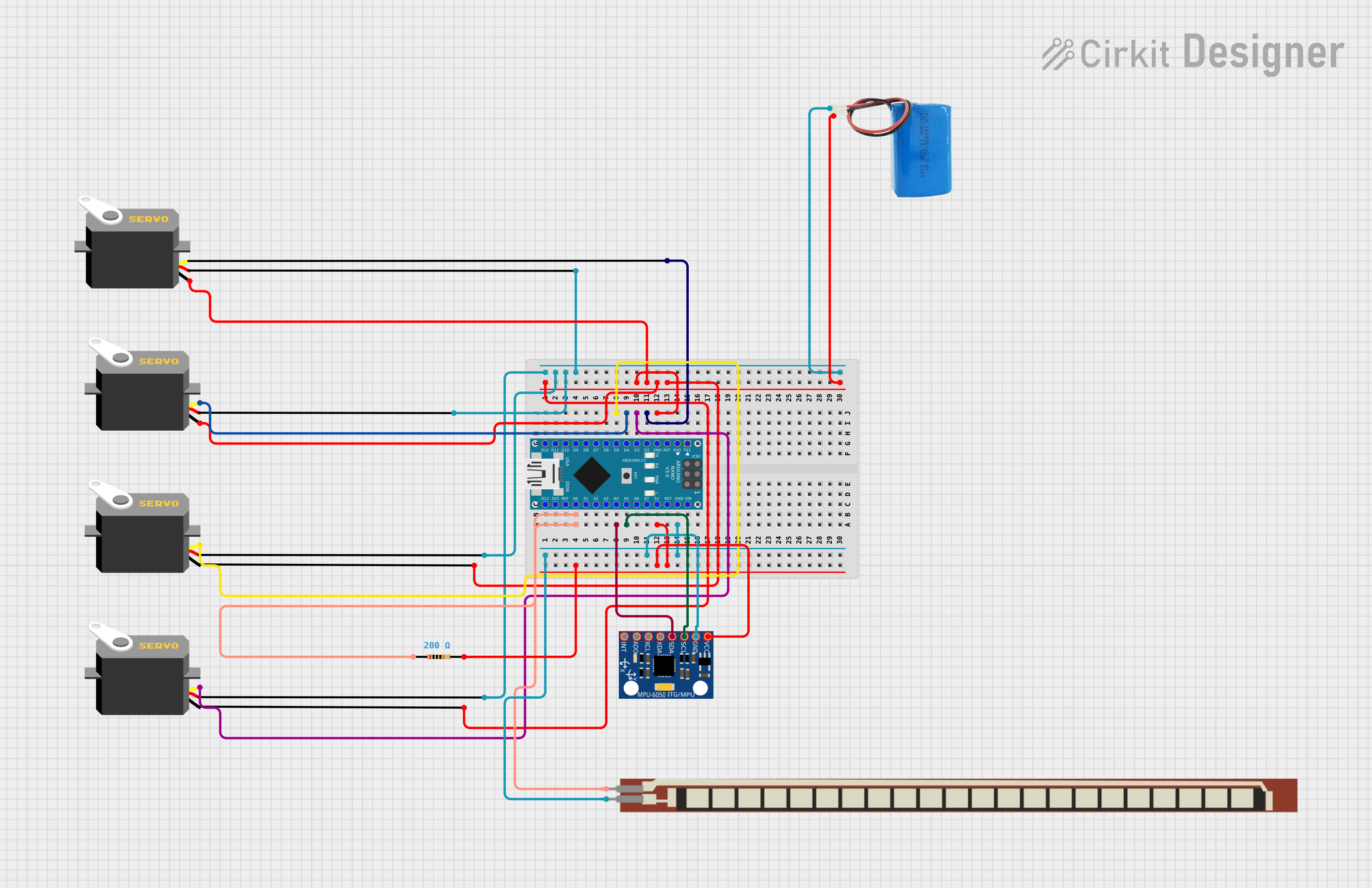
Circuit Documentation
Summary
The circuit in question is designed to control a robotic arm using gesture inputs detected by an MPU-6050 sensor. The arm is actuated by four servo motors, which are controlled by an Arduino Nano microcontroller. The MPU-6050 provides real-time feedback on the arm's orientation, which is then used to adjust the position of the servos accordingly. A flex resistor is used to control the gripper mechanism of the robotic arm. The entire system is powered by a 5V battery.
Component List
Servo Motors
- Description: Servo motors are used for precise control of angular or linear position, velocity, and acceleration. They are commonly used in robotics for actuating movements.
- Purpose: In this circuit, there are four servo motors that actuate the robotic arm's movements.
Arduino Nano
- Description: The Arduino Nano is a small, complete, and breadboard-friendly board based on the ATmega328P. It offers the same connectivity and specs of the Arduino Uno board in a smaller form factor.
- Purpose: The Arduino Nano serves as the central controller for the robotic arm, processing sensor data and controlling the servo motors.
MPU-6050
- Description: The MPU-6050 sensor contains a MEMS accelerometer and a MEMS gyro in a single chip. It is very accurate, as it contains 16-bits analog to digital conversion hardware for each channel.
- Purpose: It is used to detect the orientation and movement of the robotic arm, providing input to the Arduino for servo control.
Basic Flex Resistor
- Description: A flex resistor changes its resistance when bent. It can be used to detect bending or flexing.
- Purpose: In this circuit, it is likely used as a sensor for the gripper mechanism of the robotic arm.
Resistor (200 Ohms)
- Description: A resistor is a passive two-terminal electrical component that implements electrical resistance as a circuit element.
- Purpose: It is used to limit current or divide voltages in the circuit.
5V Battery
- Description: A power source that provides a constant 5V output.
- Purpose: It powers the Arduino Nano and the servo motors.
Wiring Details
Servo Motors
- Ground (GND): Connected to the negative terminal of the 5V battery and GND pin on the Arduino Nano.
- Power (VCC): Connected to the positive terminal of the 5V battery.
- Control (Pulse): Each servo motor's control pin is connected to a digital pin on the Arduino Nano (D2, D3, D4, D5).
Arduino Nano
- GND: Connected to the ground net, which includes the GND pins of the MPU-6050, the Basic Flex Resistor, and the negative terminal of the 5V battery.
- 5V: Connected to the 200 Ohm resistor and the VCC pin of the MPU-6050.
- A0: Connected to the Basic Flex Resistor.
- A4 (SDA): Connected to the SDA pin of the MPU-6050.
- A5 (SCL): Connected to the SCL pin of the MPU-6050.
- D2, D3, D4, D5: Connected to the control pins of the four servo motors.
MPU-6050
- VCC: Connected to the 5V output from the Arduino Nano.
- GND: Connected to the ground net.
- SDA: Connected to the A4 pin on the Arduino Nano.
- SCL: Connected to the A5 pin on the Arduino Nano.
Basic Flex Resistor
- Pin 1: Connected to the A0 pin on the Arduino Nano.
- Pin 2: Connected to the ground net.
Resistor (200 Ohms)
- Pin 1: Connected to the A0 pin on the Arduino Nano and the Basic Flex Resistor.
- Pin 2: Connected to the 5V pin on the Arduino Nano and the VCC pin of the MPU-6050.
5V Battery
- Positive: Connected to the VCC pins of the servo motors.
- Negative: Connected to the ground net.
Documented Code
//Code for Gesture Controlled Robotic ARM (Arduino Nano & MPU6050)

//Circuit Digest

#include<Wire.h>                //I2C Wire Library

#include<Servo.h>               //Servo Motor Library

Servo servo_1;
Servo servo_2;
Servo servo_3;
Servo servo_4;

const int MPU_addr=0x68;        //MPU6050 I2C Address
int16_t axis_X,axis_Y,axis_Z;
int minVal=265;
int maxVal=402;

double x;
double y;
double z;

void setup()
{
  Serial.begin(9600);

  Wire.begin();                      //Initialize I2C Communication
  Wire.beginTransmission(MPU_addr);  //Start communication with MPU6050
  Wire.write(0x6B);                  //Writes to Register 6B
  Wire.write(0);                     //Writes 0 into 6B Register to Reset
  Wire.endTransmission(true);        //Ends I2C transmission

  servo_1.attach(2);   // Forward/Reverse_Motor
  servo_2.attach(3);   // Up/Down_Motor
  servo_3.attach(4);   // Gripper_Motor
  servo_4.attach(5);   // Left/Right_Motor

}

void loop()
{
  Wire.beginTransmission(MPU_addr);
  Wire.write(0x3B);                  //Start with register 0x3B
  Wire.endTransmission(false);
  Wire.requestFrom(MPU_addr,14,true);  //Read 14 Registers

  axis_X=Wire.read()<<8|Wire.read();                //Reads the MPU6050 X,Y,Z AXIS Value
  axis_Y=Wire.read()<<8|Wire.read();
  axis_Z=Wire.read()<<8|Wire.read();

  int xAng = map(axis_X,minVal,maxVal,-90,90);     // Maps axis values in terms of -90 to +90
  int yAng = map(axis_Y,minVal,maxVal,-90,90);
  int zAng = map(axis_Z,minVal,maxVal,-90,90);

  x= RAD_TO_DEG * (atan2(-yAng, -zAng)+PI);       //Formula to convert into degree
  y= RAD_TO_DEG * (atan2(-xAng, -zAng)+PI);
  z= RAD_TO_DEG * (atan2(-yAng, -xAng)+PI);

  int gripper;
  int flex_sensorip = analogRead(A0);            //Reads flex sensor output

  if(flex_sensorip > 750)
        {
          gripper = 0;
        }
        else
        {
          gripper = 180;
        }

   servo_3.write(gripper);                    //Writes gripper value to 3rd servo motor

  if(x >=0 && x <= 60)
  {
     int mov1 = map(x,0,60,0,90);
     Serial.print("Movement in F/R = ");
     Serial.print(mov1);
     Serial.println((char)176);
     servo_1.write(mov1);
  }

  else if(x >=300 && x <= 360)
  {
     int mov2 = map(x,360,250,0,180);
     Serial.print("Movement in Up/Down = ");
     Serial.print(mov2);
     Serial.println((char)176);
     servo_2.write(mov2);
  }

 if(y >=0 && y <= 60)
  {
     int mov3 = map(y,0,60,90,180);
     Serial.print("Movement in Left = ");
     Serial.print(mov3);
     Serial.println((char)176);
     servo_4.write(mov3);
  }

  else if(y >=300 && y <= 360)
  {
     int mov3 = map(y,360,300,90,0);
     Serial.print("Movement in Right = ");
     Serial.print(mov3);
     Serial.println((char)176);
     servo_4.write(mov3);
  }
}
This code is designed to be uploaded to an Arduino Nano microcontroller. It initializes the MPU-6050 sensor and the servo motors in the setup() function. In the loop() function, it reads the sensor data, processes it, and then controls the servo motors to move the robotic arm based on the sensor input. The flex sensor reading is used to control the gripper servo.