
Raspberry Pi 4B Controlled Traffic Light System with Ambient Light Sensing
View and Edit Project In Cirkit Designer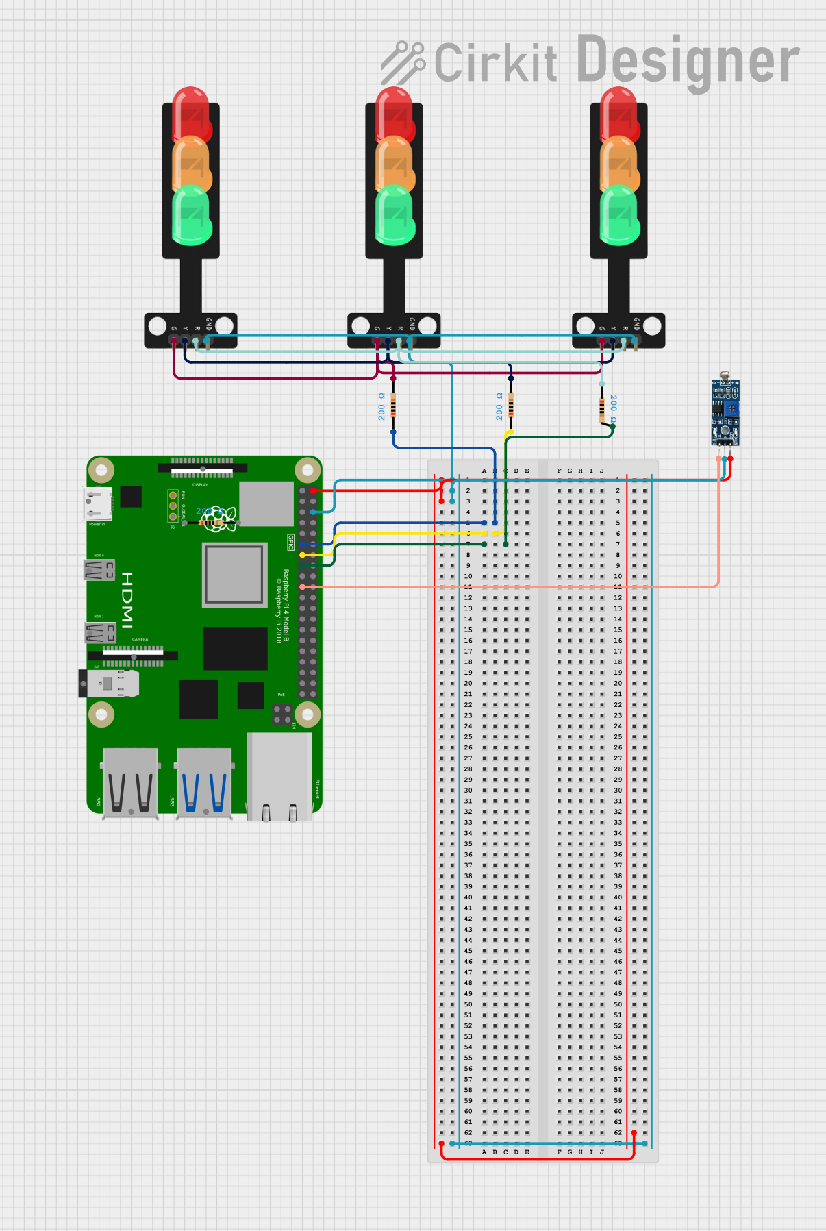
Circuit Documentation
Summary
This circuit appears to be designed to control a set of traffic lights using a Raspberry Pi 4B as the central controller. The traffic lights are likely to be used for a simulation or a small-scale model, as they are directly driven by the GPIO pins of the Raspberry Pi through resistors. An LDR (Light Dependent Resistor) module is also included in the circuit, which may be used to detect ambient light levels and adjust the operation of the traffic lights accordingly. The circuit is powered by the 5V supply from the Raspberry Pi, and all components share a common ground.
Component List
Raspberry Pi 4B
- Description: A small single-board computer with a variety of GPIO pins.
- Pins: 3V3, 5V, multiple GPIOs, GND, and others.
- Purpose: Acts as the central processing unit for controlling the traffic lights and reading from the LDR module.
Traffic Light
- Description: A simple traffic light module with three LEDs (Green, Yellow, Red).
- Pins: Green, Yellow, Red, GND.
- Purpose: Represents the traffic signal lights controlled by the Raspberry Pi.
Resistor (200 Ohms)
- Description: A resistor with a resistance of 200 Ohms.
- Purpose: Limits the current to the LEDs of the traffic lights to prevent damage.
LDR Module 3 pin
- Description: A light sensor module with a digital output.
- Pins: VCC, GND, DO.
- Purpose: Detects the ambient light level which could be used to control the traffic lights based on environmental conditions.
Wiring Details
Raspberry Pi 4B
- 5V to LDR Module VCC
- GND to Traffic Light GND, LDR Module GND
- GPIO17 to Resistor (pin1)
- GPIO27 to Resistor (pin1)
- GPIO22 to Resistor (pin2)
- GPIO10 to LDR Module DO
Traffic Light
- GND to Raspberry Pi GND
- Green to Resistor (pin2)
- Yellow to Resistor (pin2)
- Red to Resistor (pin1)
Resistor (200 Ohms)
- One end to Raspberry Pi GPIO (GPIO17, GPIO27, or GPIO22)
- The other end to Traffic Light (Green, Yellow, or Red)
LDR Module 3 pin
- VCC to Raspberry Pi 5V
- GND to Raspberry Pi GND
- DO to Raspberry Pi GPIO10
Documented Code
No code has been provided for the microcontrollers in the circuit. The expected code would likely initialize the GPIO pins on the Raspberry Pi for output to control the traffic lights and input to read from the LDR module. It would also contain the logic for the traffic light sequence and potentially adjust this sequence based on the input from the LDR module.