
Arduino-Controlled Robotic Arm with Joystick and Push Button Interface
View and Edit Project In Cirkit Designer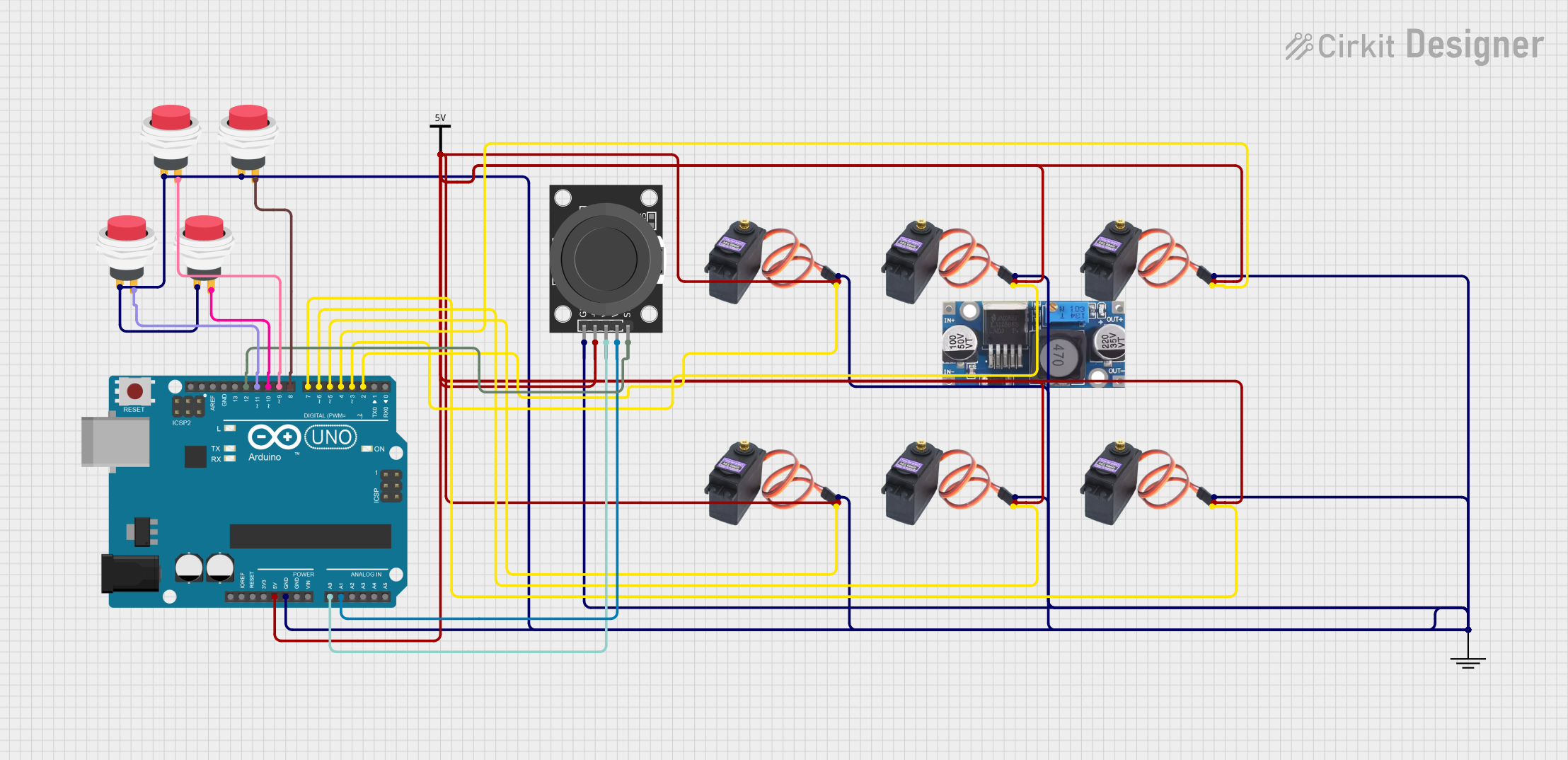
Circuit Documentation
Summary of the Circuit
This circuit is designed around an Arduino UNO microcontroller, which serves as the central processing unit. The circuit includes multiple MG996R servo motors, a KY-023 Dual Axis Joystick Module for user input, and a series of 2Pin Push Switches that likely serve as control inputs. A common Vcc net is used to distribute power to the servo motors and the joystick module, while a common ground net ensures all components share a common reference point. The servo motors are controlled via signal pins connected to various digital outputs on the Arduino UNO. The joystick module's variable resistors (VRx and VRy) are connected to analog inputs on the Arduino, and its switch (SW) is connected to a digital input. The push switches are interfaced with other digital inputs and outputs on the Arduino, suggesting they may be used to trigger events or actions in the system.
Component List
Arduino UNO
- Microcontroller board based on the ATmega328P
- Features digital I/O pins, analog input pins, and power pins
MG996R Servo Motor (Multiple Instances)
- High-torque digital servo motor
- Operates on 5V and uses a single control signal for positioning
KY-023 Dual Axis Joystick Module
- Provides two analog outputs corresponding to the X and Y axes
- Includes a pushbutton switch
2Pin Push Switch (Multiple Instances)
- Simple push-to-make switch
- Has two pins for input and output
Step down Buck Converter
- Reduces input voltage to a lower output voltage
- Includes input and output pins with ground references
Vcc and GND Components
- Represent power supply connections for the circuit
Wiring Details
Arduino UNO
5VandGNDpins are used to provide power to other components in the circuit.- Analog pins
A0andA1are connected to the joystick's VRx and VRy outputs, respectively. - Digital pin
D12is connected to the joystick's SW output. - Digital pins
D2toD11are connected to the signal pins of the MG996R servo motors and the output pins of the push switches.
MG996R Servo Motors
VCCpins are connected to the common Vcc net.GNDpins are connected to the common ground net.SIGpins are connected to individual digital pins on the Arduino UNO for control signals.
KY-023 Dual Axis Joystick Module
+5Vpin is connected to the common Vcc net.GNDpin is connected to the common ground net.VRxandVRypins are connected toA0andA1on the Arduino UNO, respectively.SWpin is connected to digital pinD12on the Arduino UNO.
2Pin Push Switches
Input +pins are connected to the common ground net.Output +pins are connected to individual digital pins on the Arduino UNO.
Step down Buck Converter
- Not explicitly connected in the provided net list, but would typically be used to step down voltage for the circuit.
Documented Code
void setup() {
  // put your setup code here, to run once:

}

void loop() {
  // put your main code here, to run repeatedly:

}
The provided code is a template with empty setup() and loop() functions, which are the standard structure for Arduino sketches. The setup() function is intended to contain initialization code that runs once when the program starts, and the loop() function should contain the main logic that runs continuously.
Additional code is required to control the servo motors, read the joystick inputs, and respond to the push switches. This would involve setting the appropriate pins as inputs or outputs using pinMode(), reading analog values with analogRead(), reading digital states with digitalRead(), and controlling servo position with a servo library and write() function calls.