ESP8266 Controlled Dual Motor Robot with Inductive Sensing
Circuit Documentation
Summary
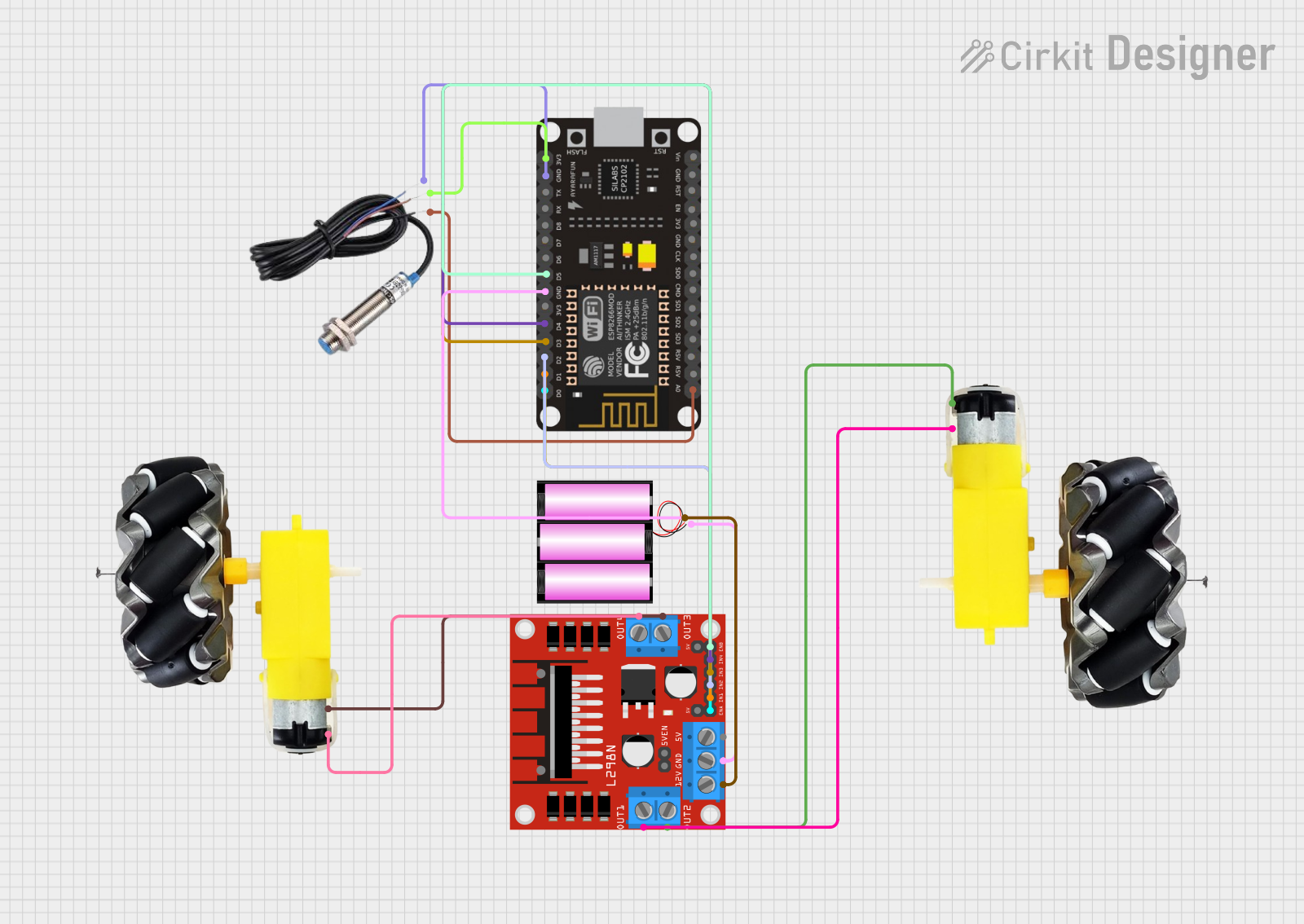
This circuit is designed to control a pair of motors with wheels using an ESP8266 NodeMCU microcontroller and an L298N DC motor driver. An inductive sensor is included to provide feedback to the microcontroller, which can be used for various purposes such as detecting metallic objects or measuring rotational speed. The motors are powered by a 12V battery, which also supplies power to the motor driver. The ESP8266 NodeMCU interfaces with the motor driver to control the speed and direction of the motors and reads the signal from the inductive sensor.
Component List
Motor and Wheels
- Description: A set of motors attached to wheels, used for providing motion.
- Pins:
vcc,GND
Inductive Sensor
- Description: A sensor that detects the presence of metallic objects or can be used for speed measurement.
- Pins:
Signal,VCC,GND
ESP8266 NodeMCU
- Description: A microcontroller with Wi-Fi capability for controlling various components in the circuit.
- Pins:
D0,D1,D2,D3,D4,3V3,GND,D5,D6,D7,D8,RX,TX,A0,RSV,SD3,SD2,SD1,CMD,SD0,CLK,EN,RST,VIN
L298N DC Motor Driver
- Description: A module that drives DC motors; it can control the direction and speed of up to two motors.
- Pins:
OUT1,OUT2,12V,GND,5V,OUT3,OUT4,5V-ENA-JMP-I,5V-ENA-JMP-O,+5V-J1,+5V-J2,ENA,IN1,IN2,IN3,IN4,ENB
Battery 12V
- Description: A 12V battery used to power the motors and the motor driver.
- Pins:
+,-
Wiring Details
Motor and Wheels
- vcc: Connected to
OUT2andOUT4of the L298N DC motor driver. - GND: Connected to
OUT1andOUT3of the L298N DC motor driver.
Inductive Sensor
- Signal: Connected to
A0on the ESP8266 NodeMCU. - VCC: Connected to
3V3on the ESP8266 NodeMCU. - GND: Connected to
GNDon the ESP8266 NodeMCU.
ESP8266 NodeMCU
- D0: Connected to
ENAon the L298N DC motor driver. - D1: Connected to
IN1on the L298N DC motor driver. - D2: Connected to
IN2on the L298N DC motor driver. - D3: Connected to
IN3on the L298N DC motor driver. - D4: Connected to
IN4on the L298N DC motor driver. - D5: Connected to
ENBon the L298N DC motor driver. - 3V3: Connected to
VCCon the Inductive Sensor. - GND: Common ground with the L298N DC motor driver and the Inductive Sensor.
- A0: Connected to
Signalon the Inductive Sensor.
L298N DC Motor Driver
- OUT1, OUT2: Connected to one set of
motor and wheels. - OUT3, OUT4: Connected to another set of
motor and wheels. - ENA, ENB: Control signals from ESP8266 NodeMCU (
D0andD5). - IN1, IN2, IN3, IN4: Direction control signals from ESP8266 NodeMCU (
D1,D2,D3,D4). - 12V: Connected to the
+of the 12V battery. - GND: Common ground with the ESP8266 NodeMCU and the 12V battery.
Battery 12V
- +: Connected to
12Von the L298N DC motor driver. - -: Common ground with the L298N DC motor driver and the ESP8266 NodeMCU.
Documented Code
Since no code was provided in the input, this section is left blank. When code is available, it should be documented here with explanations of how the microcontroller interfaces with the other components, including the motor driver and the inductive sensor. The code would typically include setup routines, main control loops, interrupt service routines, and any necessary functions to read from or write to the connected components.