
Arduino and ESP32-Based Smart Sensor System with GPS and GSM Connectivity
View and Edit Project In Cirkit Designer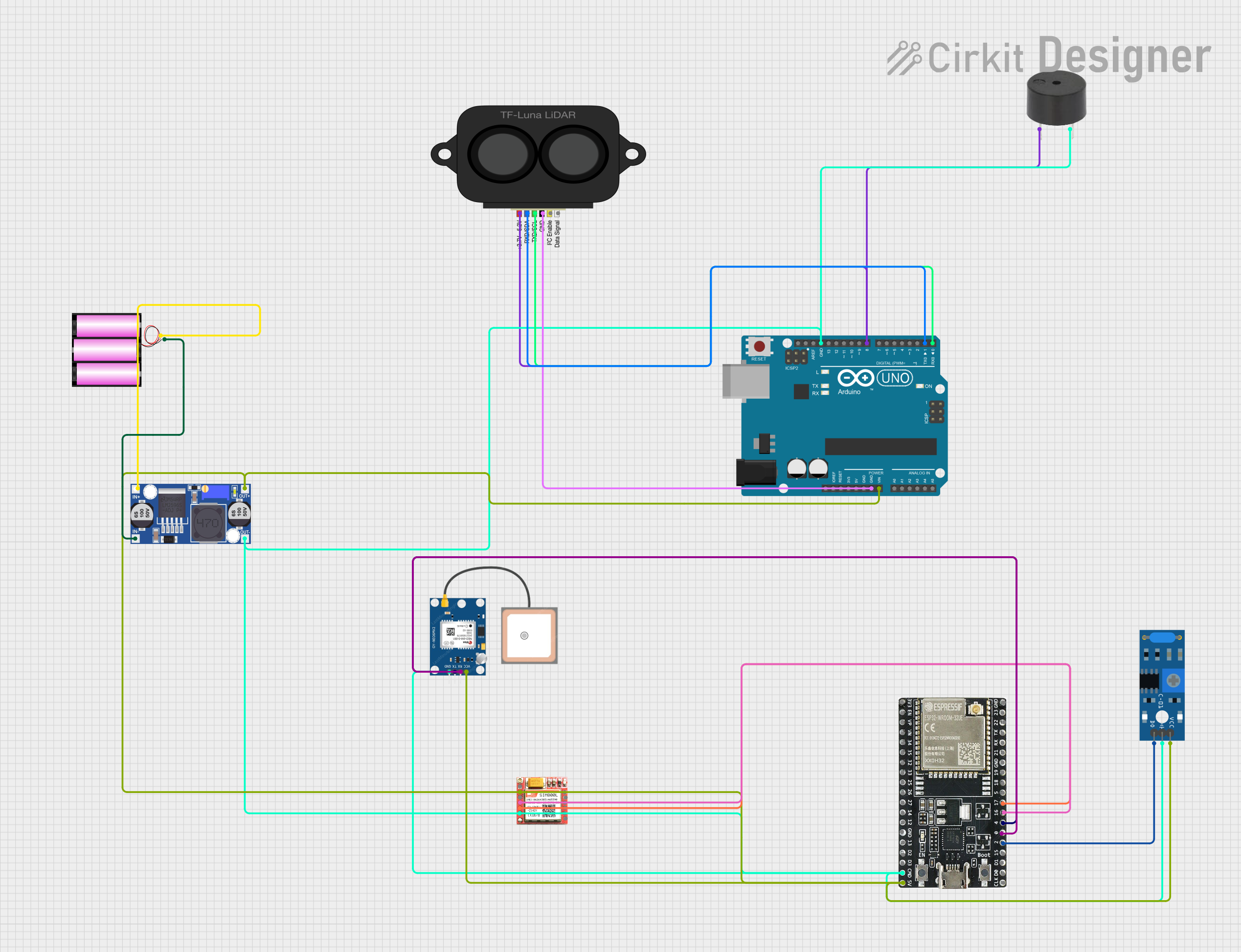
Circuit Documentation
Summary
This document provides a detailed overview of a circuit that integrates various components including an Arduino UNO, ESP32-WROOM-32UE, TF LUNA LIDAR, GPS NEO 6M, SIM 800L, SW-420 Vibration Sensor, a buzzer, a 12V battery, and a Buck converter. The circuit is designed to interface these components for a specific application, with power management and communication handled through the microcontrollers.
Component List
Arduino UNO
- Description: A microcontroller board based on the ATmega328P.
- Pins: UNUSED, IOREF, Reset, 3.3V, 5V, GND, Vin, A0, A1, A2, A3, A4, A5, SCL, SDA, AREF, D13, D12, D11, D10, D9, D8, D7, D6, D5, D4, D3, D2, D1, D0
Buzzer
- Description: An audio signaling device.
- Pins: PIN, GND
TF LUNA LIDAR
- Description: A LIDAR sensor for distance measurement.
- Pins: power, RXD/SDA, TXD/SCL, GND, ICL, DATA SIG
ESP32-WROOM-32UE
- Description: A powerful Wi-Fi and Bluetooth microcontroller.
- Pins: 3v3, EN, VP, VN, 34, 35, 32, 33, 25, 26, 27, 14, 12, GND, 13, D2, D3, 5V, 23, 22, TX, RX, 21, 19, 18, 5, 17, 16, 4, 0, 2, 15, D1, D0, CKL
GPS NEO 6M
- Description: A GPS module for location tracking.
- Pins: VCC, RX, TX, GND
SIM 800L
- Description: A GSM/GPRS module for communication.
- Pins: NFT, RING, VCC, DTR, RST, MIC +, RXD, MIC-, TXD, SPK+, GND, SPK-
SW-420 Vibration Sensor
- Description: A vibration sensor for detecting vibrations.
- Pins: vcc, Ground, Digital output
Battery 12V
- Description: A 12V power source.
- Pins: +, -
Buck Converter
- Description: A DC-DC converter to step down voltage.
- Pins: IN+, IN-, OUT+, OUT-
Wiring Details
Arduino UNO
- GND connected to GND of TF LUNA LIDAR, Buck converter, SW-420 Vibration Sensor, GPS NEO 6M, SIM 800L, buzzer, and ESP32-WROOM-32UE.
- Vin connected to OUT+ of Buck converter.
- D8 connected to power of TF LUNA LIDAR and PIN of buzzer.
- D1 connected to RXD/SDA of TF LUNA LIDAR.
- D0 connected to TXD/SCL of TF LUNA LIDAR.
Buzzer
- PIN connected to D8 of Arduino UNO.
- GND connected to GND of Buck converter.
TF LUNA LIDAR
- GND connected to GND of Arduino UNO.
- power connected to D8 of Arduino UNO.
- RXD/SDA connected to D1 of Arduino UNO.
- TXD/SCL connected to D0 of Arduino UNO.
ESP32-WROOM-32UE
- 5V connected to OUT+ of Buck converter.
- GND connected to GND of Buck converter.
- 17 connected to TXD of SIM 800L.
- 16 connected to RXD of SIM 800L.
- 4 connected to TX of GPS NEO 6M.
- 0 connected to RX of GPS NEO 6M.
- 2 connected to Digital output of SW-420 Vibration Sensor.
GPS NEO 6M
- VCC connected to OUT+ of Buck converter.
- GND connected to GND of Buck converter.
- TX connected to 4 of ESP32-WROOM-32UE.
- RX connected to 0 of ESP32-WROOM-32UE.
SIM 800L
- VCC connected to OUT+ of Buck converter.
- GND connected to GND of Buck converter.
- TXD connected to 17 of ESP32-WROOM-32UE.
- RXD connected to 16 of ESP32-WROOM-32UE.
SW-420 Vibration Sensor
- vcc connected to OUT+ of Buck converter.
- Ground connected to GND of Buck converter.
- Digital output connected to 2 of ESP32-WROOM-32UE.
Battery 12V
- + connected to IN+ of Buck converter.
- - connected to IN- of Buck converter.
Buck Converter
- IN+ connected to + of Battery 12V.
- IN- connected to - of Battery 12V.
- OUT+ connected to Vin of Arduino UNO, vcc of SW-420 Vibration Sensor, VCC of GPS NEO 6M, VCC of SIM 800L, and 5V of ESP32-WROOM-32UE.
- OUT- connected to GND of Arduino UNO, Ground of SW-420 Vibration Sensor, GND of GPS NEO 6M, GND of SIM 800L, GND of buzzer, and GND of ESP32-WROOM-32UE.
Documented Code
Arduino UNO Code
void setup() {
  // put your setup code here, to run once:

}

void loop() {
  // put your main code here, to run repeatedly:

}
Additional Documentation
This documentation provides a comprehensive overview of the circuit, including the components used, their wiring details, and the code for the microcontrollers.