
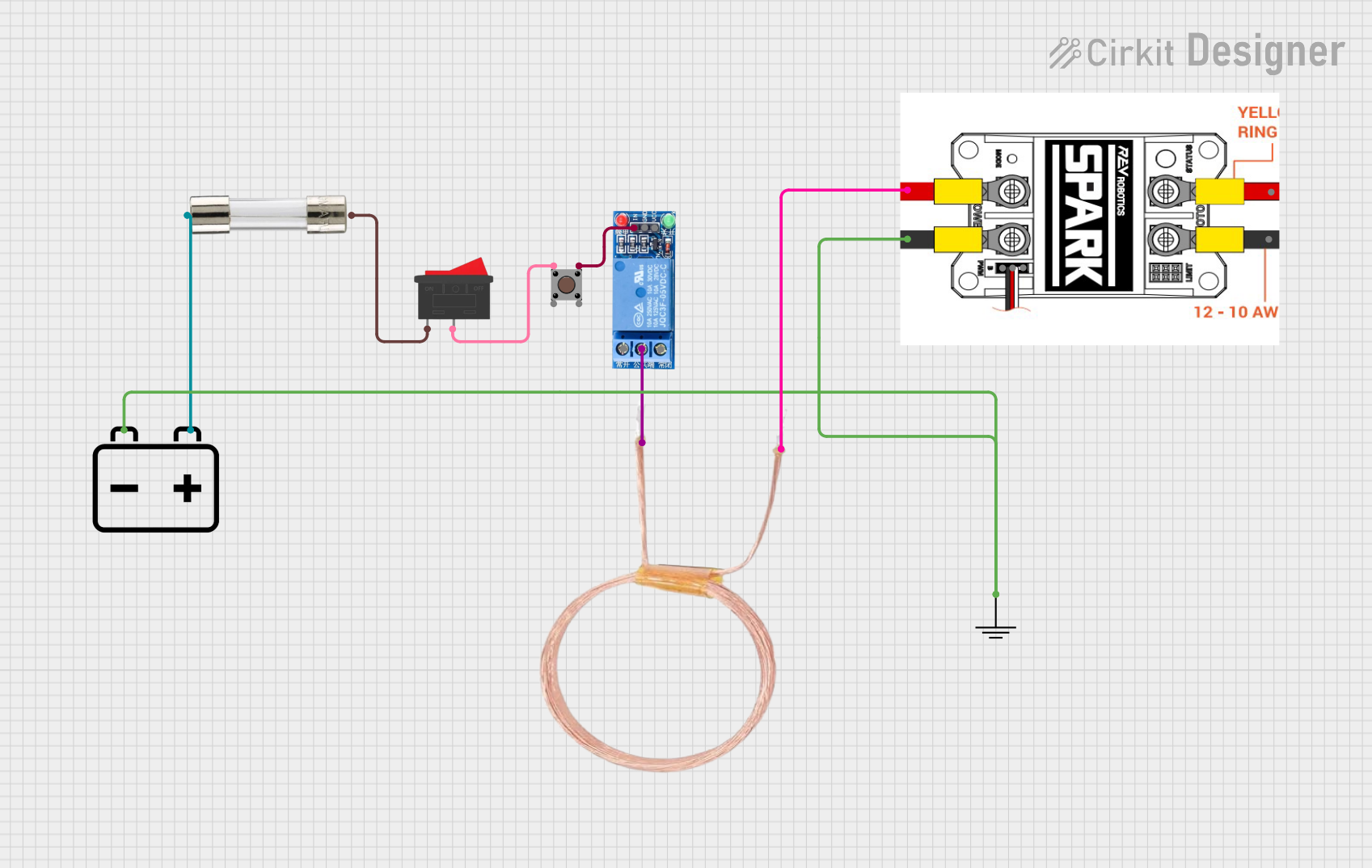
Circuit Documentation
Summary
This document provides a detailed overview of a circuit that includes a 1 Channel Relay, a Pushbutton, a Fuse, a Copper Coil, a 12V Battery, a Spark module, and a Rocker Switch. The circuit is designed to control a load through a relay, which is activated by a pushbutton and protected by a fuse. The Spark module is used to generate a spark, and the entire circuit is powered by a 12V battery.
Component List
1 Channel Relay 5V
- Pins: VCC, GND, IN, NC, COM, NO
- Description: A relay module that allows a low voltage circuit to switch a higher voltage circuit.
- Purpose: To control the connection of the load.
GND
- Pins: GND
- Description: Ground connection.
- Purpose: To provide a common ground reference for the circuit.
Pushbutton
- Pins: Pin 3 (out), Pin 4 (out), Pin 1 (in), Pin 2 (in)
- Description: A simple pushbutton switch.
- Purpose: To manually activate the relay.
Fuse
- Pins: Terminal 1, Terminal 2
- Description: A protective device that breaks the circuit if the current exceeds a certain threshold.
- Purpose: To protect the circuit from overcurrent.
Copper Coil - 30 Turns
- Pins: 1 PIN, 2 PIN
- Description: A coil of wire used to generate a magnetic field.
- Purpose: To generate a magnetic field when current flows through it.
12V Battery
- Pins: -, +
- Description: A 12V power source.
- Purpose: To provide power to the circuit.
Spark
- Pins: V+, V-, GND, VCC, PWM, M+, M-
- Description: A module used to generate a spark.
- Purpose: To generate a spark for ignition or other purposes.
Rocker Switch
- Pins: 1, 2
- Description: A switch that rocks back and forth to open or close a circuit.
- Purpose: To control the power to the pushbutton and relay.
Wiring Details
1 Channel Relay 5V
- IN is connected to Pin 3 (out) of the Pushbutton.
- COM is connected to 1 PIN of the Copper Coil - 30 Turns.
GND
- GND is connected to V- of the Spark and - of the 12V Battery.
Pushbutton
- Pin 3 (out) is connected to IN of the 1 Channel Relay 5V.
- Pin 1 (in) is connected to 2 of the Rocker Switch.
Fuse
- Terminal 1 is connected to + of the 12V Battery.
- Terminal 2 is connected to 1 of the Rocker Switch.
Copper Coil - 30 Turns
- 1 PIN is connected to COM of the 1 Channel Relay 5V.
- 2 PIN is connected to V+ of the Spark.
12V Battery
- - is connected to GND.
- + is connected to Terminal 1 of the Fuse.
Spark
- V+ is connected to 2 PIN of the Copper Coil - 30 Turns.
- V- is connected to GND.
Rocker Switch
- 1 is connected to Terminal 2 of the Fuse.
- 2 is connected to Pin 1 (in) of the Pushbutton.
Code
There is no microcontroller code associated with this circuit.
This document provides a comprehensive overview of the circuit, including a summary, detailed component list, wiring details, and code documentation.