
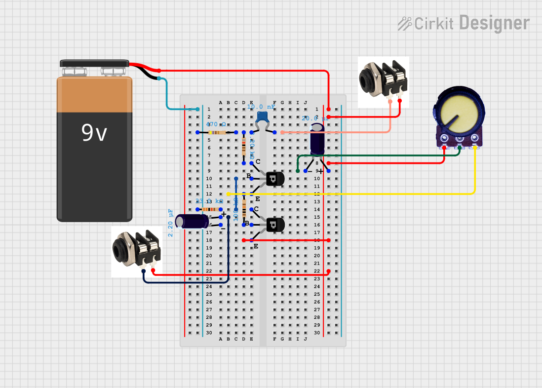
Circuit Documentation
Summary of the Circuit
This circuit appears to be an analog electronic circuit that may be used for signal processing or conditioning. The presence of transistors, resistors, capacitors, and potentiometers suggests that this circuit could be part of an amplifier, filter, or a power supply module. However, without a specific schematic or design goal, the exact function of the circuit cannot be determined. The circuit includes a 9V battery for power, various passive components for signal manipulation, and transistors that could be used for switching or amplification.
Component List
Passive Components
- 9V Battery: Provides the power supply for the circuit.
- Resistors: There are several resistors with different resistance values used for current limiting, voltage division, or biasing transistors.
- Resistor (470 Ohms)
- Resistor (8.2 kOhms)
- Resistor (33 kOhms)
- Resistor (100 kOhms)
- Ceramic Capacitor: A non-polarized capacitor with a capacitance of 10 nF, likely used for noise filtering or timing purposes.
- Electrolytic Capacitors: Polarized capacitors with different capacitance values, possibly used for power supply filtering or coupling/decoupling applications.
- Electrolytic Capacitor (2.2 µF)
- Electrolytic Capacitor (20 µF)
- Potentiometer: A variable resistor that can be adjusted to change the resistance, often used for controlling voltage or current in a circuit.
Active Components
- PNP Transistors (CBE): Bipolar junction transistors that could be used for switching or amplifying signals.
Connectors
- Unbalanced Jacks: Connectors that could be used for audio input/output or for connecting external signals to the circuit.
Miscellaneous
- Comments: Placeholder components that may represent annotations or notes in the circuit design.
Wiring Details
9V Battery
- Positive terminal connected to the emitter of a PNP transistor and the positive terminal of an electrolytic capacitor.
- Negative terminal connected to a series of resistors.
Resistors
- 470 Ohm resistor connected between the negative terminal of the battery and other resistors.
- 8.2 kOhm resistor connected between a ceramic capacitor and a PNP transistor's collector.
- 33 kOhm resistor connected to the base of a PNP transistor and an electrolytic capacitor.
- 100 kOhm resistor connected to the emitter of a PNP transistor and a potentiometer.
Ceramic Capacitor
- One pin connected to an unbalanced jack (Tip).
- The other pin connected to an 8.2 kOhm resistor.
Electrolytic Capacitors
- 2.2 µF capacitor connected between the base of a PNP transistor and a 33 kOhm resistor.
- 20 µF capacitor connected to a potentiometer (Output).
PNP Transistors (CBE)
- One transistor has its collector connected to an 8.2 kOhm resistor and another transistor's collector.
- The base of the same transistor is connected to a 33 kOhm resistor and an electrolytic capacitor.
- The emitter is connected to a 100 kOhm resistor and a potentiometer (VCC).
Potentiometer
- GND pin connected to the negative side of the circuit (battery, electrolytic capacitor, unbalanced jacks).
- Output pin connected to a 20 µF electrolytic capacitor.
- VCC pin connected to the emitter of a PNP transistor and a 100 kOhm resistor.
Unbalanced Jacks
- Tip of one jack connected to a ceramic capacitor.
- Tip of another jack connected to the positive terminal of an electrolytic capacitor.
- Sleeves of both jacks connected to the negative side of the circuit.
Documented Code
There is no code provided for any microcontrollers in the circuit. This section is left blank as no embedded code is associated with the current circuit design. If in the future, a microcontroller or any programmable device is added to the circuit, the code will be documented here.