
Arduino-Controlled Ultrasonic Sensor with Servos, LDR, Buzzer, and Laser Module
View and Edit Project In Cirkit Designer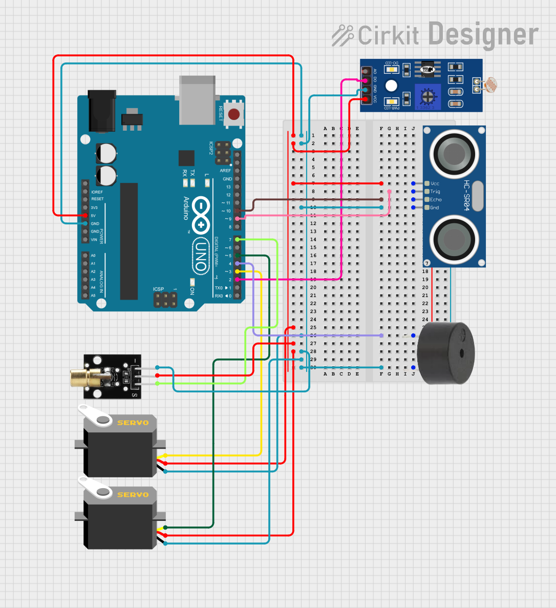
Circuit Documentation
Summary
This circuit integrates various components including an HC-SR04 Ultrasonic Sensor, two Servo motors, an LDR (Light Dependent Resistor), a buzzer, a KY-008 Laser Emitter, and an Arduino UNO microcontroller. The circuit is designed to perform tasks that likely involve distance measurement, light sensing, audio signaling, laser emission, and motor control. The Arduino UNO serves as the central processing unit, controlling the peripherals through its digital and analog I/O pins.
Component List
HC-SR04 Ultrasonic Sensor
- Description: A sensor that measures distance by emitting ultrasonic waves and measuring the time taken for the echo to return.
- Pins: VCC, TRIG, ECHO, GND
Servo Motor
- Description: An actuator that can be precisely controlled for angular rotation.
- Pins: GND, VCC, PULSE
LDR (Light Dependent Resistor)
- Description: A sensor that changes resistance based on the ambient light level.
- Pins: A0, D0, GND, VCC
Buzzer
- Description: An audio signaling device that emits sound when powered.
- Pins: PIN, GND
KY-008 Laser Emitter
- Description: A module that emits a laser beam when powered.
- Pins: SIG, 5V, GND
Arduino UNO
- Description: A microcontroller board based on the ATmega328P, widely used for building digital devices and interactive objects.
- Pins: UNUSED, IOREF, Reset, 3.3V, 5V, GND, Vin, A0-A5, SCL, SDA, AREF, D0-D13
Wiring Details
HC-SR04 Ultrasonic Sensor
- VCC connected to Arduino UNO 5V
- TRIG connected to Arduino UNO D9
- ECHO connected to Arduino UNO D10
- GND connected to common ground
Servo Motors
- VCC connected to Arduino UNO 5V
- GND connected to common ground
- PULSE connected to Arduino UNO D5 (Servo 1) and D3 (Servo 2)
LDR (Light Dependent Resistor)
- VCC connected to Arduino UNO 5V
- D0 connected to Arduino UNO D2
- GND connected to common ground
Buzzer
- PIN connected to Arduino UNO D4
- GND connected to common ground
KY-008 Laser Emitter
- SIG connected to Arduino UNO D7
- 5V connected to Arduino UNO 5V
- GND connected to common ground
Documented Code
Arduino UNO Code (sketch.ino)
void setup() {
  // put your setup code here, to run once:

}

void loop() {
  // put your main code here, to run repeatedly:

}
Additional Notes
- The provided code is a template and does not contain any functional implementation.
- The actual behavior of the circuit will be determined by the code that is written and uploaded to the Arduino UNO.
- The code should be written to initialize the pins, define the main logic in the
setup()function, and implement the continuous behavior in theloop()function. - The documentation file (documentation.txt) is empty and can be used to add further explanations or instructions related to the code and circuit operation.