
Arduino UNO Based Environmental Monitoring System with Gas Detection and Alert
View and Edit Project In Cirkit Designer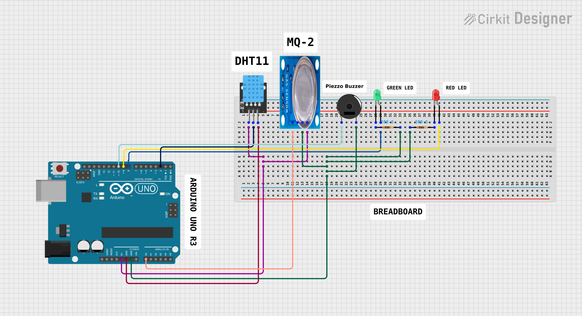
Circuit Documentation
Summary
This circuit is designed around an Arduino UNO microcontroller and includes various sensors and output devices. The primary sensor is a DHT11, which measures temperature and humidity. An MQ-5 gas sensor is used to detect the presence of gases such as LPG, natural gas, and coal gas. Output devices include a piezo buzzer and two LEDs (red and green). The circuit is powered by the Arduino UNO's 5V output, and ground connections are shared among components. The Arduino UNO reads sensor data and controls the LEDs and buzzer based on the sensor inputs.
Component List
- Arduino UNO: A microcontroller board based on the ATmega328P, with digital and analog I/O pins.
- DHT11: A basic, ultra low-cost digital temperature and humidity sensor.
- MQ-5 Gas Sensor: A gas sensor designed for detecting LPG, natural gas, and coal gas.
- Piezo Buzzer: An electronic device that produces sound when an electrical signal is applied.
- Resistor (200 Ohms): Two resistors used to limit current through the LEDs.
- LED (Green): A green light-emitting diode used as an indicator.
- LED (Red): A red light-emitting diode used as an indicator.
Wiring Details
Arduino UNO
- 5V: Powers the DHT11 and MQ-5 sensors.
- GND: Common ground for DHT11, MQ-5, Piezo Buzzer, and both LEDs.
- A0: Connected to the analog output of the MQ-5 sensor.
- D2: Connected to the signal pin of the DHT11 sensor.
- D8: Connected to the anode of the green LED through a 200 Ohm resistor.
- D9: Connected to the anode of the red LED through a 200 Ohm resistor.
- D10: Connected to one terminal of the Piezo Buzzer.
DHT11
- 5V: Power supply.
- S: Signal pin connected to D2 on the Arduino UNO.
- GND: Ground connection.
MQ-5 Gas Sensor
- VCC: Power supply (5V from Arduino UNO).
- GND: Ground connection.
- Analog out: Connected to A0 on the Arduino UNO.
Piezo Buzzer
- Pin 1: Connected to D10 on the Arduino UNO.
- Pin 2: Ground connection.
Resistor (200 Ohms)
- Pin 1: Connected to the cathode of the corresponding LED.
- Pin 2: Connected to the ground (common ground with Arduino UNO).
LED (Green)
- Anode: Connected to D8 on the Arduino UNO through a 200 Ohm resistor.
- Cathode: Connected to the ground through a 200 Ohm resistor.
LED (Red)
- Anode: Connected to D9 on the Arduino UNO through a 200 Ohm resistor.
- Cathode: Connected to the ground through a 200 Ohm resistor.
Documented Code
#include <DHT.h>
#define DHTPIN 2          // Define the pin connected to the DHT11 sensor
#define DHTTYPE DHT11     // Specify the type of DHT sensor
DHT dht(DHTPIN, DHTTYPE);
#define MQ5_PIN A0        // Define the pin connected to the MQ-5 sensor
#define RED_LED_PIN 8     // Define the pin connected to the red LED
#define GREEN_LED_PIN 9   // Define the pin connected to the green LED
#define BUZZER_PIN 10     // Define the pin connected to the buzzer
#define MOTION_PIN 3      // Define the pin connected to the motion sensor (not included in the wiring details)

void setup() {
  Serial.begin(9600);    // Start serial communication at 9600 baud
  dht.begin();           // Initialize the DHT sensor
  pinMode(MOTION_PIN, INPUT);       // Set the motion sensor pin as input
  pinMode(RED_LED_PIN, OUTPUT);     // Set the red LED pin as output
  pinMode(GREEN_LED_PIN, OUTPUT);   // Set the green LED pin as output
  pinMode(BUZZER_PIN, OUTPUT);      // Set the buzzer pin as output
}

void loop() {
  float h = dht.readHumidity();          // Read humidity value
  float t = dht.readTemperature();       // Read temperature value
  int mq5Value = analogRead(MQ5_PIN);    // Read the value from the MQ-5 sensor
  int motion_Detected = digitalRead(MOTION_PIN);  // Read the motion sensor value

  // Print the sensor values to the serial monitor
  Serial.print("Humidity: ");
  Serial.print(h);
  Serial.print("%  Temperature: ");
  Serial.print(t);
  Serial.print("°C  MQ-5 Value: ");
  Serial.println(mq5Value);
  Serial.print("\tMotion Detected:");
  Serial.println(motion_Detected);

  // Control the LEDs and buzzer based on the MQ-5 sensor value
  if (mq5Value > 150) {
    digitalWrite(RED_LED_PIN, HIGH);
    digitalWrite(GREEN_LED_PIN, LOW);
    tone(BUZZER_PIN, 1000);  // Sound the buzzer
  } else {
    digitalWrite(RED_LED_PIN, LOW);
    digitalWrite(GREEN_LED_PIN, HIGH);
    noTone(BUZZER_PIN);       // Stop the buzzer
  }

  // If motion is detected, turn on both LEDs briefly
  if (motion_Detected) {
    digitalWrite(GREEN_LED_PIN, HIGH);
    digitalWrite(RED_LED_PIN, HIGH);
    delay(50);
  }

  delay(2000);  // Wait for 2 seconds before reading the sensors again
}
This code is designed to read temperature and humidity from the DHT11 sensor, detect gas levels with the MQ-5 sensor, and detect motion (although the motion sensor is not included in the wiring details). The red and green LEDs, as well as the buzzer, are controlled based on the readings from the MQ-5 sensor. If the gas level is above a certain threshold, the red LED is turned on, the green LED is turned off, and the buzzer is sounded. If the gas level is below the threshold, the green LED is turned on, and the red LED and buzzer are turned off. If motion is detected, both LEDs are turned on for a brief moment.