Arduino UNO Controlled Sensor Suite with Visual and Auditory Feedback
Circuit Documentation
Summary
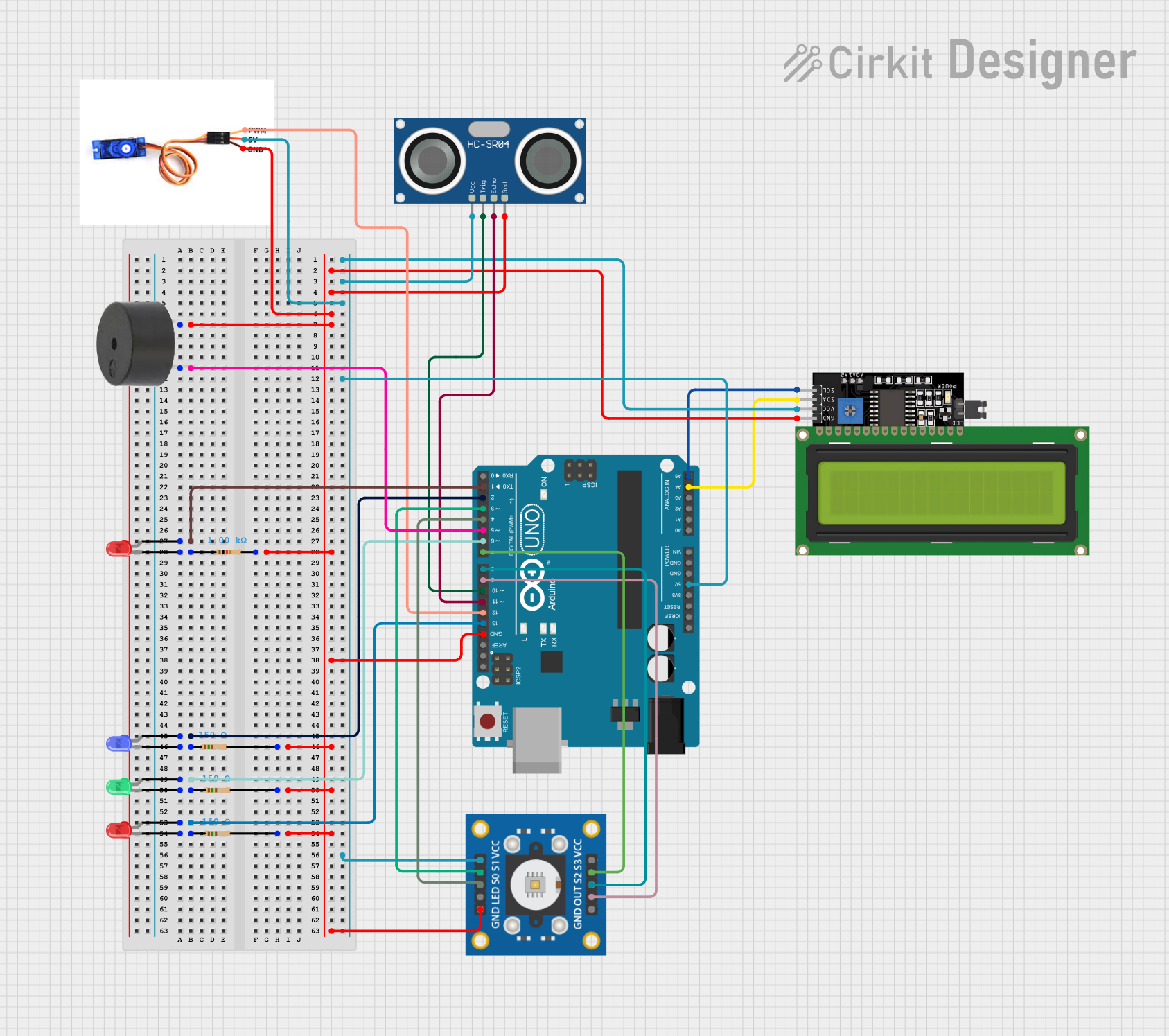
This document provides a detailed overview of a circuit designed to interface various components with an Arduino UNO microcontroller. The circuit includes LEDs of different colors, resistors with varying resistance values, an LCD display with I2C interface, a servo motor, a buzzer, a color sensor (tcs3200), and an ultrasonic sensor (HC-SR04). The Arduino UNO serves as the central processing unit, controlling the peripherals through its digital and analog I/O pins.
Component List
LEDs
- Red LED: A two-pin light-emitting diode that emits red light.
- Green LED: A two-pin light-emitting diode that emits green light.
- Blue LED: A two-pin light-emitting diode that emits blue light.
Resistors
- 150 Ohm Resistor: Limits current to protect connected LEDs.
- 1k Ohm Resistor: Provides a higher level of current limitation.
LCD Display
- LCD Display 16x4 I2C: A 16x4 character LCD display with an I2C interface for displaying text and numbers.
Servo Motor
- SG90 Servo Motor: A small and lightweight servo motor capable of precise position control.
Buzzer
- Buzzer: An electromechanical component that emits sound when powered.
Color Sensor
- tcs3200: A color sensor that detects the color of objects and provides a frequency output corresponding to the color.
Microcontroller
- Arduino UNO: A microcontroller board based on the ATmega328P, with a variety of digital and analog I/O pins.
Ultrasonic Sensor
- HC-SR04 Ultrasonic Sensor: Measures distance by emitting ultrasonic waves and timing their reflection.
Wiring Details
LEDs
- Red LED: Anode connected to Arduino's D1, cathode connected to a 150 Ohm resistor.
- Green LED: Anode connected to Arduino's D6, cathode connected to a 150 Ohm resistor.
- Blue LED: Anode connected to Arduino's D2, cathode connected to a 150 Ohm resistor.
Resistors
- 150 Ohm Resistors: One end connected to the cathode of each LED (red, green, and blue), the other end connected to the ground.
- 1k Ohm Resistor: Connected to the cathode of a red LED.
LCD Display
- LCD Display 16x4 I2C: SCL connected to Arduino's A5, SDA connected to Arduino's A4, VCC connected to Arduino's 5V, and GND connected to ground.
Servo Motor
- SG90 Servo Motor: PWM connected to Arduino's D12, 5V to Arduino's 5V, and GND to ground.
Buzzer
- Buzzer: PIN connected to Arduino's D5, GND to ground.
Color Sensor
- tcs3200: OUT connected to Arduino's D9, S2 to D8, S3 to D7, S0 to D4, S1 to D3, VCC to Arduino's 5V, and GND to ground.
Ultrasonic Sensor
- HC-SR04 Ultrasonic Sensor: TRIG connected to Arduino's D10, ECHO to D11, VCC to Arduino's 5V, and GND to ground.
Documented Code
void setup() {
  // put your setup code here, to run once:

}

void loop() {
  // put your main code here, to run repeatedly:

}
The provided code is a template for the Arduino UNO microcontroller. The setup() function is intended for initialization code that runs once at the start, while the loop() function contains code that runs continuously. Specific functionality must be added to these functions to control the connected components as per the requirements of the circuit's application.