
Circuit Documentation
Summary
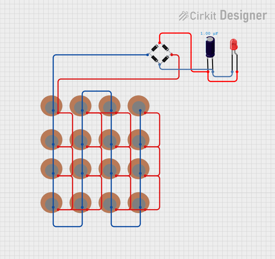
This circuit consists of multiple piezo sensors, a bridge rectifier, an electrolytic capacitor, and a red LED. The piezo sensors are connected in parallel and feed into the bridge rectifier, which converts the AC signal from the sensors into a DC signal. The DC signal is then filtered by the capacitor and used to power the LED.
Component List
Piezo Sensor
- Description: A piezoelectric sensor that generates a voltage when mechanical stress is applied.
- Pins: +, -
LED: Two Pin (red)
- Description: A red light-emitting diode (LED) that emits light when current flows through it.
- Pins: Cathode, Anode
Electrolytic Capacitor
- Description: A capacitor with a capacitance of 1 µF used for filtering the DC signal.
- Pins: +, -
- Properties:
- Capacitance: 1 µF
Bridge Rectifier
- Description: A bridge rectifier that converts AC to DC.
- Pins: Source_in-, Source_in+, Source_out-, Source_out+
Wiring Details
Piezo Sensor
Pin + is connected to:
- Pin + of all other piezo sensors
- Pin source_out- of the bridge rectifier
Pin - is connected to:
- Pin - of all other piezo sensors
- Pin source_out+ of the bridge rectifier
LED: Two Pin (red)
Pin Anode is connected to:
- Pin - of the electrolytic capacitor
- Pin Source_in- of the bridge rectifier
Pin Cathode is connected to:
- Pin + of the electrolytic capacitor
- Pin Source_in+ of the bridge rectifier
Electrolytic Capacitor
Pin - is connected to:
- Pin Anode of the LED
- Pin Source_in- of the bridge rectifier
Pin + is connected to:
- Pin Cathode of the LED
- Pin Source_in+ of the bridge rectifier
Bridge Rectifier
Pin Source_in- is connected to:
- Pin - of the electrolytic capacitor
- Pin Anode of the LED
Pin Source_in+ is connected to:
- Pin + of the electrolytic capacitor
- Pin Cathode of the LED
Pin Source_out- is connected to:
- Pin + of all piezo sensors
Pin Source_out+ is connected to:
- Pin - of all piezo sensors
Code
No microcontroller code is provided for this circuit.
This documentation provides a comprehensive overview of the circuit, including a summary, detailed component list, and wiring details. The components are described individually, and their connections are clearly outlined to ensure proper assembly and understanding of the circuit.