Cirkit Designer
Your all-in-one circuit design IDE
Home /
Project Documentation
Arduino Nano RGB LED Controller with Battery Power
Circuit Documentation
Summary
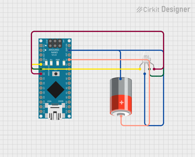
This circuit consists of an Arduino Nano microcontroller, a 5V battery, and an RGB LED. The Arduino Nano is used to control the RGB LED, which is powered by the 5V battery. The RGB LED can display different colors based on the signals received from the Arduino Nano.
Component List
5V Battery
- Description: A power source providing 5 volts.
- Pins: +, -
RGB LED (Wokwi compatible)
- Description: An RGB LED with four pins: Red (R), Common (COM), Green (G), and Blue (B).
- Pins: R, COM, G, B
Arduino Nano
- Description: A small, complete, and breadboard-friendly microcontroller board based on the ATmega328P.
- Pins: D1/TX, D0/RX, RESET, GND, D2, D3, D4, D5, D6, D7, D8, D9, D10, D11/MOSI, D12/MISO, VIN, 5V, A7, A6, A5, A4, A3, A2, A1, A0, AREF, 3V3, D13/SCK
Wiring Details
5V Battery
- + Pin:
- Connected to the 5V pin of the Arduino Nano.
- - Pin:
- Connected to the COM pin of the RGB LED.
- Connected to the GND pin of the Arduino Nano.
RGB LED (Wokwi compatible)
- R Pin:
- Connected to the D2 pin of the Arduino Nano.
- COM Pin:
- Connected to the - pin of the 5V battery.
- Connected to the GND pin of the Arduino Nano.
- G Pin:
- Connected to the D3 pin of the Arduino Nano.
- B Pin:
- Connected to the D4 pin of the Arduino Nano.
Arduino Nano
- 5V Pin:
- Connected to the + pin of the 5V battery.
- GND Pin:
- Connected to the COM pin of the RGB LED.
- Connected to the - pin of the 5V battery.
- D2 Pin:
- Connected to the R pin of the RGB LED.
- D3 Pin:
- Connected to the G pin of the RGB LED.
- D4 Pin:
- Connected to the B pin of the RGB LED.
Code Documentation
Arduino Nano Code
void setup() {
  int Rled = 2;
  int Gled = 3;
  int Bled = 4;
  pinMode(Rled, OUTPUT);
  pinMode(Gled, OUTPUT);
  pinMode(Bled, OUTPUT);
}

void loop() {
  int Rled = 2;
  int Gled = 3;
  int Bled = 4;
  digitalWrite(Gled, HIGH);
  digitalWrite(Rled, LOW);
  digitalWrite(Bled, HIGH);
  digitalWrite(Gled, LOW);
  digitalWrite(Rled, HIGH);
  digitalWrite(Bled, LOW);
}
This code initializes the RGB LED pins (D2, D3, and D4) as outputs in the setup() function. In the loop() function, it alternates the states of the RGB LED pins to create different colors.