Solar-Powered Environmental Monitoring System with Safety Alarms and Automated Control
Circuit Documentation
Summary
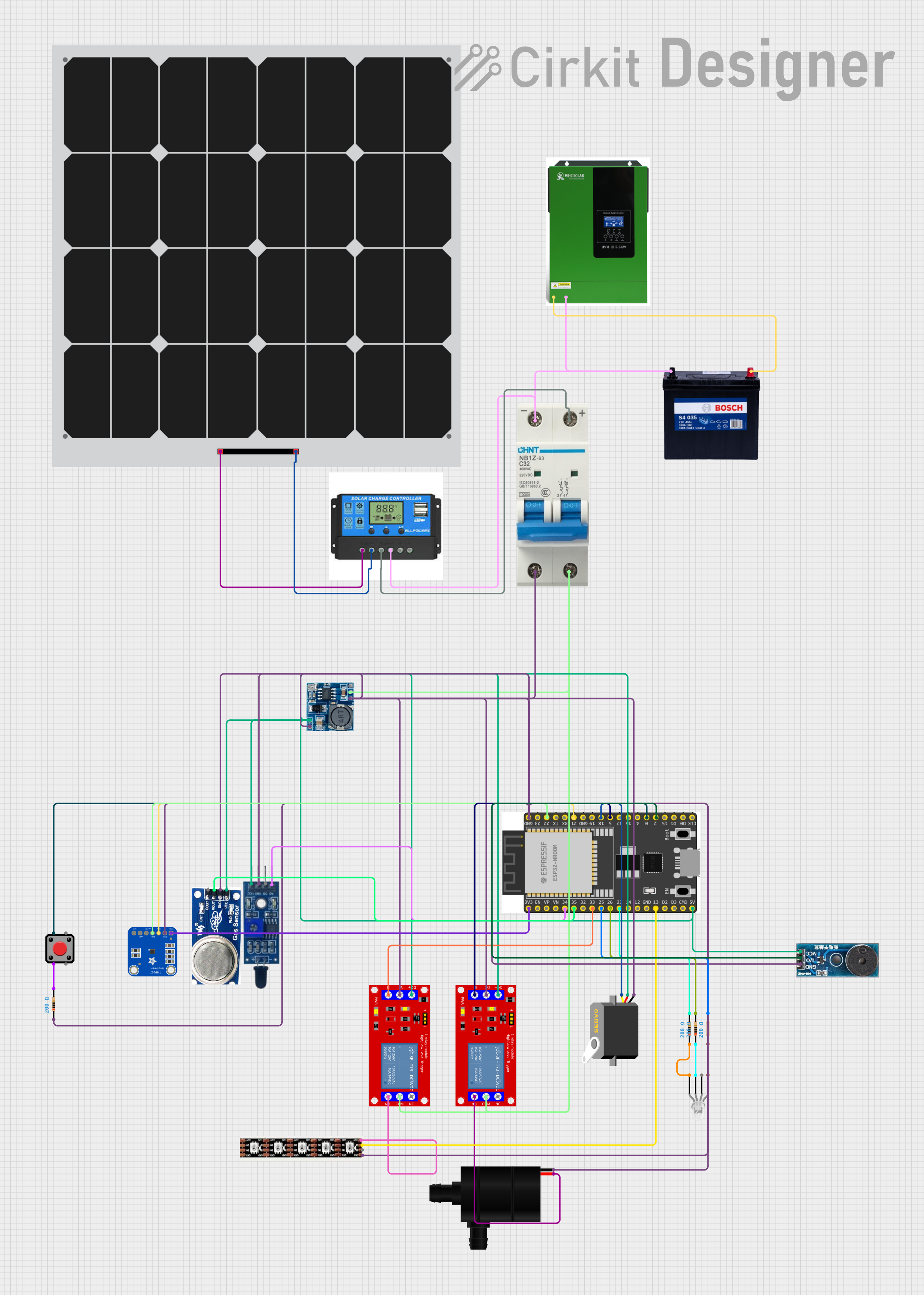
This circuit is designed to harness solar energy through a solar panel, manage power distribution using a charge controller, and power various components including sensors, a microcontroller, a water pump, LEDs, and a servo motor. The system is controlled by an ESP32 microcontroller, which interfaces with temperature and smoke sensors, a flame sensor, and controls a water pump and LEDs via relay modules. The circuit includes a 12V battery for energy storage and a solar inverter to convert DC to AC power. Safety features include a circuit breaker to protect against overcurrent conditions.
Component List
Power Components
- 12V 200Ah Battery: Stores electrical energy for the circuit.
- Solar Panel: Converts sunlight into electrical energy.
- Charge Controller: Manages the charging of the battery from the solar panel and provides overcharge protection.
- Solar Inverter: Converts DC power from the battery into AC power.
- Step down Module: Converts higher voltage levels to a regulated 5V output.
Control Components
- ESP 32 Wroom Dev Kit: A microcontroller development board used for controlling various components in the circuit.
Sensors
- TMP007 Thermopile Sensor: Measures temperature without contact by absorbing infrared energy from an object.
- Smoke Sensor: Detects the presence of smoke particles in the air.
- Flame Sensor: Detects the presence of a flame or fire.
Actuators
- Water Pump: Pumps water when activated.
- Servo: A motor that can be precisely controlled for position.
Indicators and Interfaces
- LED: Four Pin (Common Cathode): A multi-color LED that can display various colors.
- Buzzer Module: Emits an audible alert when activated.
- Pushbutton: A manual switch used for user input.
Protection and Switching
- Circuit Breaker: Protects the circuit from overcurrent by interrupting the flow of electricity when a fault is detected.
- 1 Channel 5V Relay Module: Electrically operated switches that allow the microcontroller to control higher power loads.
Miscellaneous
- Resistor: Limits the current flow and divides voltages within the circuit.
- WS2815 LED Strip: A strip of individually controllable RGB LEDs.
Wiring Details
Power Components
12V 200Ah Battery
12Vconnected to the Solar InverterB+and the Charge ControllerBattery Positive.GNDconnected to the Solar InverterB-, the Charge ControllerBattery Negative, and various GND connections throughout the circuit.
Solar Panel
+connected to the Charge ControllerSolar Positive.-connected to the Charge ControllerSolar Negative.
Charge Controller
Solar PositiveandSolar Negativeconnected to the Solar Panel.Battery PositiveandBattery Negativeconnected to the 12V Battery and the Circuit Breaker.
Solar Inverter
B+connected to the 12V Battery12V.B-connected to the 12V BatteryGND.
Step down Module
24v IN+not connected in the provided net list.12v IN+connected to the Circuit Breaker+.5v OUT+and5v OUT-connected to various VCC and GND connections in the circuit.
Control Components
- ESP 32 Wroom Dev Kit
3V3connected to the TMP007 Thermopile SensorVCC.GNDconnected to various GND connections in the circuit.GPIOpins connected to various components for control and data acquisition.
Sensors
TMP007 Thermopile Sensor
VCCconnected to the ESP323V3.GNDconnected to the common GND net.SDAandSCLconnected to the ESP32 for I2C communication.
Smoke Sensor
VCCconnected to the 5V supply from the Step down Module.GNDconnected to the common GND net.AOconnected to the ESP32 for analog data acquisition.
Flame Sensor
VCCconnected to the 5V supply from the Step down Module.GNDconnected to the common GND net.A0connected to the ESP32 for analog data acquisition.
Actuators
Water Pump
VCCconnected to the Normally Open (N.O.) contact of a Relay Module.GNDconnected to the common GND net.
Servo
vccconnected to the 5V supply from the Step down Module.gndconnected to the common GND net.pulseconnected to the ESP32 for PWM control.
Indicators and Interfaces
LED: Four Pin (Common Cathode)
red anode,green anode, andblue anodeeach connected to a resistor, which is then connected to the ESP32.common cathodeconnected to the common GND net.
Buzzer Module
Vccconnected to the 5V supply from the Step down Module.GNDconnected to the common GND net.I/Oconnected to the ESP32 for control.
Pushbutton
Pin 2connected to a resistor, which is then connected to the common GND net.Pin 1connected to the ESP32 for input detection.
Protection and Switching
Circuit Breaker
+connected to the Charge ControllerBattery Positiveand the COM contacts of the Relay Modules.-connected to the Charge ControllerBattery Negativeand the common GND net.
1 Channel 5V Relay Module
VCC+connected to the 5V supply from the Step down Module.VCC- (GND)connected to the common GND net.INconnected to the ESP32 for control.N.O.connected to the Water PumpVCCand the WS2815 LED Strip+12V.COMconnected to the Circuit Breaker+.
Miscellaneous
Resistor
- Connected in series with the LED anodes and the ESP32 GPIO pins for current limiting.
WS2815 LED Strip
GNDconnected to the common GND net.B0andD0connected to the ESP32 for control.+12Vconnected to the Normally Open (N.O.) contact of a Relay Module.
Documented Code
No code was provided for the microcontroller(s) in the circuit. Therefore, this section is left blank until the relevant code is supplied for documentation.