
Circuit Documentation
Summary
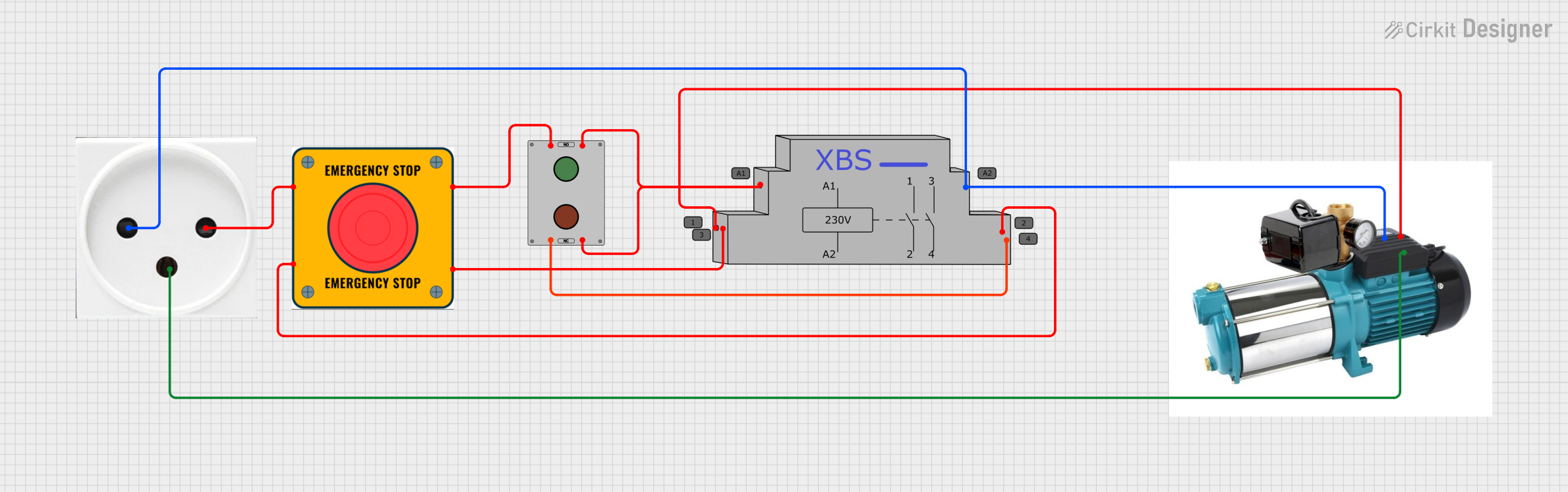
The circuit in question appears to be a control circuit for a pump (Pompa) that is connected to a power outlet. It includes an emergency stop (E Stop), a contactor (Stycznik), and a switch (Włącznik). The circuit is designed to control the power supply to the pump, with the ability to interrupt the power using the emergency stop or the switch. The contactor is used to enable or disable the power to the pump based on the control inputs from the switch and the emergency stop. The circuit does not include any microcontroller code, indicating that the control is purely electromechanical.
Component List
Power Outlet (IL)
- Pins: N (Neutral), L (Live), GND (Ground)
- Description: A standard power outlet for providing AC power to the circuit.
Pompa (Pump)
- Pins: Neutral, Faza (Phase), Obudowa (Housing)
- Description: The main actuator in the circuit, which is the pump that needs to be controlled.
E Stop (Emergency Stop)
- Pins: NO 1 (Normally Open 1), NO 2 (Normally Open 2), NC 1 (Normally Closed 1), NC 2 (Normally Closed 2)
- Description: A safety device that can be used to immediately stop the pump in case of an emergency.
Stycznik (Contactor)
- Pins: 1, 3, A1, 2, 4, A2
- Description: An electromechanical relay used to switch the electrical power to the pump.
Włącznik (Switch)
- Pins: 1 NO (Normally Open), 2 NO (Normally Open), 1 NC (Normally Closed), 2 NC (Normally Closed)
- Description: A control device used to manually start or stop the pump.
Wiring Details
Power Outlet (IL)
- Neutral (N): Connected to the Neutral pin of the Pompa and the A2 pin of the Stycznik.
- Live (L): Connected to the NO 1 pin of the E Stop.
- Ground (GND): Connected to the Obudowa pin of the Pompa.
Pompa (Pump)
- Neutral: Connected to the Neutral pin of the Power Outlet (IL).
- Faza (Phase): Connected to pin 1 of the Stycznik.
- Obudowa (Housing): Connected to the Ground pin of the Power Outlet (IL).
E Stop (Emergency Stop)
- NO 1 (Normally Open 1): Connected to the Live pin of the Power Outlet (IL).
- NO 2 (Normally Open 2): Connected to the 1 NO pin of the Włącznik.
- NC 1 (Normally Closed 1): Connected to pin 2 of the Stycznik.
- NC 2 (Normally Closed 2): Connected to pin 3 of the Stycznik.
Stycznik (Contactor)
- 1: Connected to the Faza pin of the Pompa.
- 3: Connected to the NC 2 pin of the E Stop.
- A1: Connected to the 2 NO and 2 NC pins of the Włącznik.
- 2: Connected to the NC 1 pin of the E Stop.
- 4: Connected to the 1 NC pin of the Włącznik.
- A2: Connected to the Neutral pin of the Power Outlet (IL).
Włącznik (Switch)
- 1 NO (Normally Open): Connected to the NO 2 pin of the E Stop.
- 2 NO (Normally Open): Connected to the A1 pin of the Stycznik.
- 1 NC (Normally Closed): Connected to the 4 pin of the Stycznik.
- 2 NC (Normally Closed): Connected to the A1 pin of the Stycznik.
Code Documentation
There is no embedded code provided for this circuit, as it operates purely on electromechanical principles without the use of a microcontroller.