Cirkit Designer
Your all-in-one circuit design IDE
Home /
Project Documentation
Wi-Fi Controlled Servo Motor System with ESP32 and PCA9685
Circuit Documentation
Summary
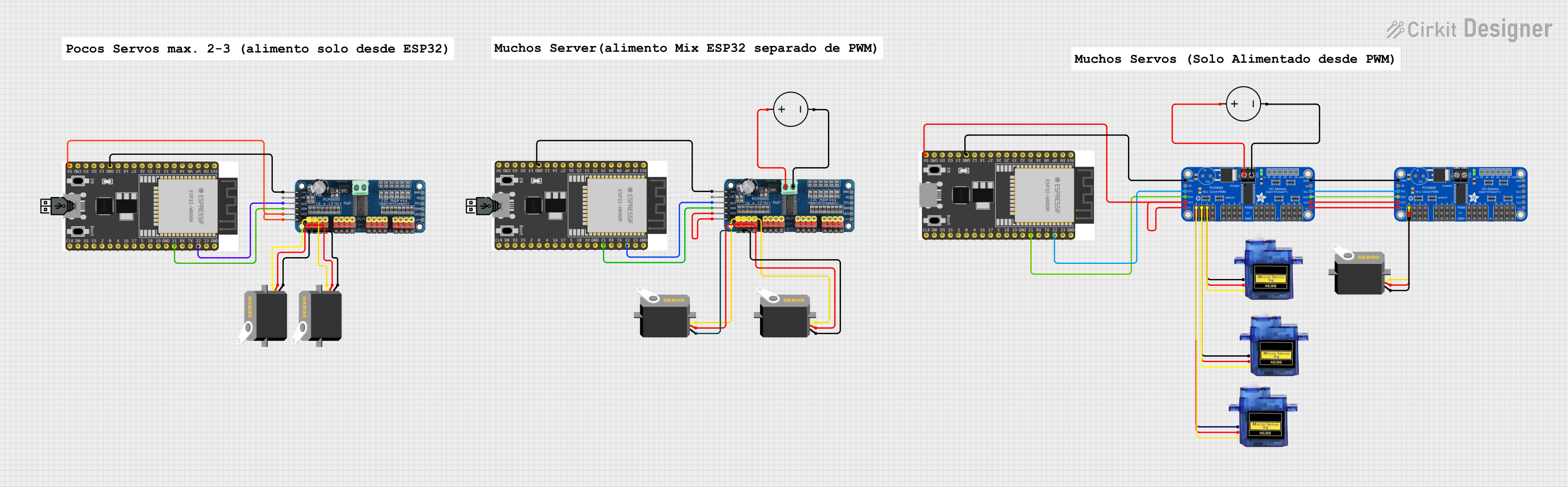
This circuit involves multiple components including Adafruit PCA9685 PWM Servo Breakouts, Micro servos, a DC Power Source, an ESP32 Wroom Dev Kit, and a 16-Channel PWM Servo Driver. The circuit is designed to control multiple servos using PWM signals generated by the PCA9685 and 16-Channel PWM Servo Driver, which are in turn controlled by the ESP32 microcontroller. The power is supplied by a DC Power Source.
Component List
Adafruit PCA9685 PWM Servo Breakout
- Description: A 16-channel PWM driver that can control servos and LEDs.
- Pins: 5.0V, GND, PWRIN, PWM0-PWM15, VCC, SDA, SCL, OE
Micro Servo 9G
- Description: A small servo motor used for precise control of angular position.
- Pins: GND, +5V, PWM
DC Power Source
- Description: Provides the necessary power for the circuit.
- Pins: Ground, Positive
ESP32 Wroom Dev Kit
- Description: A powerful microcontroller with Wi-Fi and Bluetooth capabilities.
- Pins: NOP, EN, VP, VN, GPIO 0-35, V5, 3V3, GND, TXD, RXD
16-Channel PWM Servo Driver
- Description: A driver that can control up to 16 servos using PWM signals.
- Pins: V+, VCC, SDA, SCL, OE, GND, Vin+, Vin-, PWM1-PWM16
Wiring Details
Adafruit PCA9685 PWM Servo Breakout
- PWRIN connected to Positive of DC Power Source
- GND connected to Ground of DC Power Source
- PWM0 connected to PWM of Micro Servo 9G
- 5.0V connected to +5V of Micro Servo 9G
- GND connected to GND of Micro Servo 9G
- PWM1 connected to PWM of Micro Servo 9G
- 5.0V connected to +5V of Micro Servo 9G
- GND connected to GND of Micro Servo 9G
- PWM2 connected to PWM of Micro Servo 9G
- 5.0V connected to +5V of Micro Servo 9G
- GND connected to GND of Micro Servo 9G
- 5.0V connected to VCC of Adafruit PCA9685 PWM Servo Breakout
- SDA connected to GPIO 21 of ESP32 Wroom Dev Kit
- SCL connected to GPIO 22 of ESP32 Wroom Dev Kit
- GND connected to NOP of ESP32 Wroom Dev Kit
Micro Servo 9G
- PWM connected to PWM0 of Adafruit PCA9685 PWM Servo Breakout
- +5V connected to 5.0V of Adafruit PCA9685 PWM Servo Breakout
- GND connected to GND of Adafruit PCA9685 PWM Servo Breakout
DC Power Source
- Positive connected to PWRIN of Adafruit PCA9685 PWM Servo Breakout
- Ground connected to GND of Adafruit PCA9685 PWM Servo Breakout
ESP32 Wroom Dev Kit
- V5 connected to 5.0V of Adafruit PCA9685 PWM Servo Breakout
- GPIO 21 connected to SDA of Adafruit PCA9685 PWM Servo Breakout
- GPIO 22 connected to SCL of Adafruit PCA9685 PWM Servo Breakout
- NOP connected to GND of Adafruit PCA9685 PWM Servo Breakout
16-Channel PWM Servo Driver
- GND connected to gnd of Servo
- V+ connected to vcc of Servo
- PWM1 connected to pulse of Servo
- V+ connected to VCC of 16-Channel PWM Servo Driver
- SDA connected to GPIO 21 of ESP32 Wroom Dev Kit
- SCL connected to GPIO 22 of ESP32 Wroom Dev Kit
- GND connected to NOP of ESP32 Wroom Dev Kit
- Vin+ connected to Positive of DC Power Source
- Vin- connected to Ground of DC Power Source
- PWM2 connected to pulse of Servo
- GND connected to gnd of Servo
- V+ connected to vcc of Servo
Code
No code is provided for this circuit.
This documentation provides a comprehensive overview of the circuit, including a summary, component list, wiring details, and code section. Each component and its connections are clearly described to ensure proper understanding and implementation.