Raspberry Pi 5-Controlled Robotics Platform with IR Obstacle Detection and Camera
Circuit Documentation
Summary
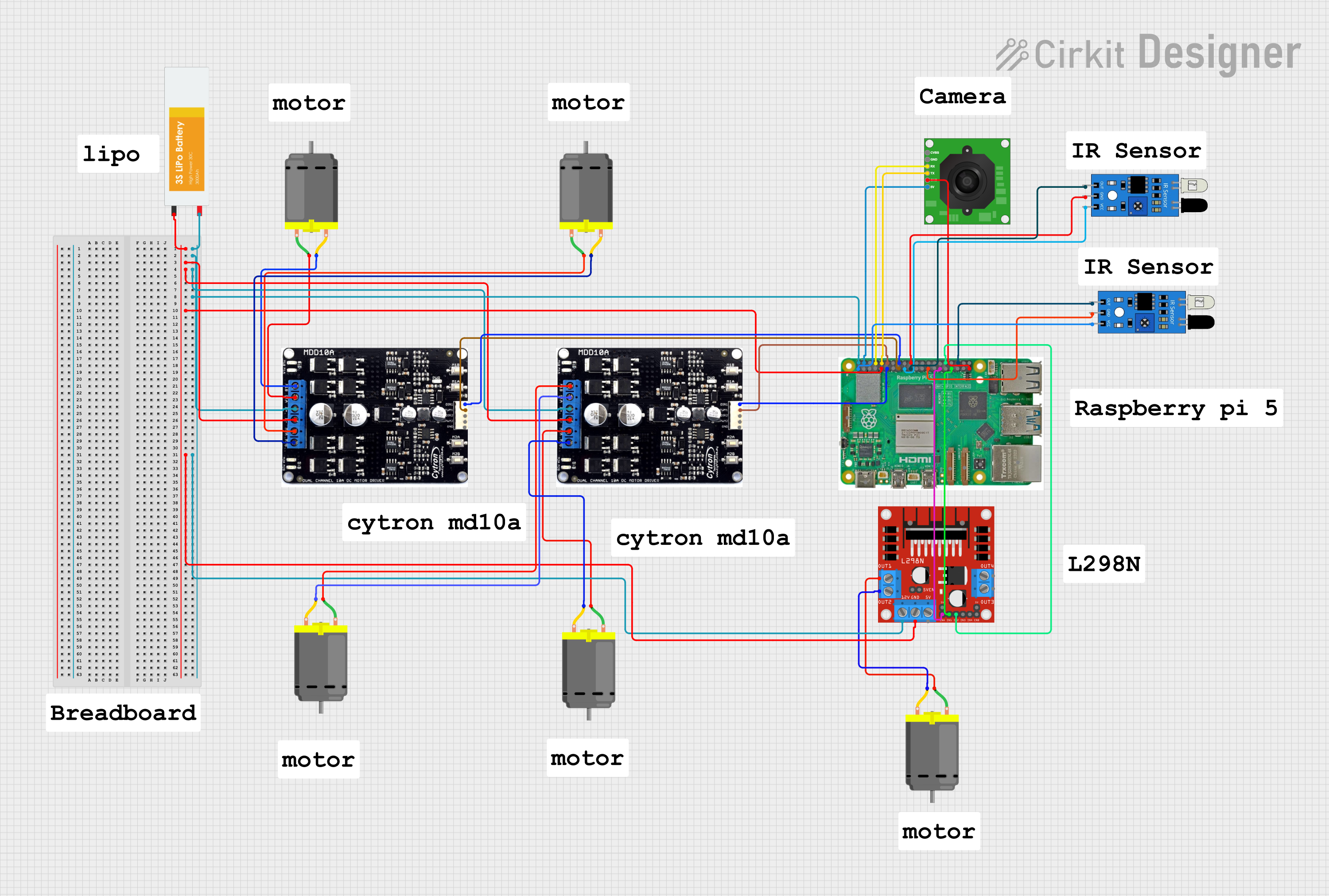
The circuit in question appears to be a motor control system with multiple DC motors, motor drivers, sensors, and a Raspberry Pi 5 for control and communication. The system is powered by a Lipo Battery and includes interfacing with IR sensors and a TTL Serial JPEG Camera. The motor drivers are used to control the direction and speed of the motors based on inputs from the Raspberry Pi GPIO pins. The IR sensors are likely used for object detection or distance measurement, and the camera for image capture.
Component List
Cytron Motor Driver
- Description: A dual-channel motor driver capable of driving two DC motors.
- Pins: m1b, m1a, b+, b-, m2a, m2b, dir1, pwm1, dir2, pwm2, gnd
DC Motor
- Description: A standard DC motor used for motion in the system.
- Pins: pin 1, pin 2
Lipo Battery
- Description: A rechargeable battery providing power to the circuit.
- Pins: VCC, GND
L298N DC Motor Driver
- Description: A motor driver capable of driving high current motors.
- Pins: OUT1, OUT2, 12V, GND, 5V, OUT3, OUT4, 5V-ENA-JMP-I, 5V-ENA-JMP-O, +5V-J1, +5V-J2, ENA, IN1, IN2, IN3, IN4, ENB
IR Sensor
- Description: An infrared sensor used for detecting objects or measuring distances.
- Pins: out, gnd, vcc
TTL Serial JPEG Camera
- Description: A camera module capable of capturing images and sending them over a serial connection.
- Pins: GND, RX, TX, CVBS, 5V
Raspberry Pi 5
- Description: A microcomputer used for controlling the circuit and processing data from sensors and the camera.
- Pins: Various GPIO pins, power, and ground.
Wiring Details
Cytron Motor Driver
- Power: Connected to the Lipo Battery's VCC and GND.
- Motor Connections: Each channel (m1a/m1b and m2a/m2b) is connected to a DC Motor.
- Control Signals: dir1 and pwm1 are connected to the Raspberry Pi GPIO pins for direction and speed control.
DC Motor
- Connections: Each motor is connected to a motor driver channel.
Lipo Battery
- Connections: Provides power to the motor drivers and the Raspberry Pi.
L298N DC Motor Driver
- Power: Connected to the Lipo Battery's 12V and GND.
- Motor Connections: OUT1 and OUT2 are connected to a DC Motor.
- Control Signals: ENA, IN1, and IN2 are connected to the Raspberry Pi GPIO pins for enabling and controlling the motor.
IR Sensor
- Power: Connected to the Raspberry Pi's 3.3V and GND.
- Signal: The output pin is connected to a GPIO pin on the Raspberry Pi.
TTL Serial JPEG Camera
- Power: Connected to the Raspberry Pi's 5V and GND.
- Data: RX and TX are connected to corresponding GPIO pins on the Raspberry Pi for serial communication.
Raspberry Pi 5
- Connections: Provides control signals to motor drivers, reads signals from IR sensors, and communicates with the camera.
Documented Code
No code was provided for the microcontrollers in the circuit. The Raspberry Pi would typically run a Python script or a similar program to control the GPIO pins based on the logic required for the application. This would include setting up the pins, reading sensor inputs, controlling motor speeds and directions, and handling communication with the camera.