
Arduino Mega 2560-Controlled Servo System with Flex Sensor Feedback and Li-ion Battery Power
View and Edit Project In Cirkit Designer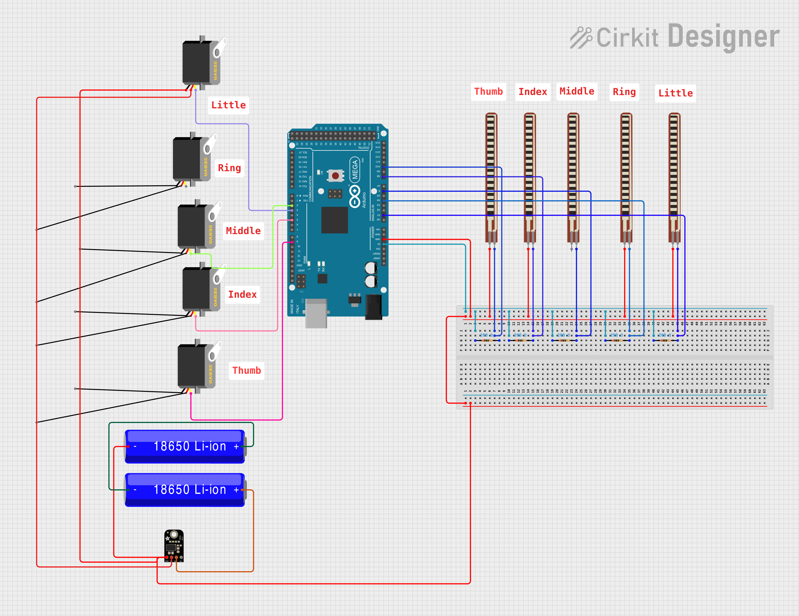
Circuit Documentation
Summary
This circuit is designed to control multiple servo motors using an Arduino Mega 2560 microcontroller. The circuit includes a power supply system using 18650 Li-ion batteries and an Adafruit MPM3610 5V buck converter to provide a stable 5V supply. Flex resistors are used as input devices, and their values are read by the Arduino's analog pins. The circuit also includes several resistors that are likely used for voltage division or current limiting purposes.
Component List
Microcontroller
- Arduino Mega 2560: A microcontroller board based on the ATmega2560, with numerous digital and analog I/O pins.
Power Supply
- 18650 Li-ion Battery: Rechargeable batteries providing the power source for the circuit.
- Adafruit MPM3610 5V Buck Converter: A DC-DC converter that steps down the voltage to a stable 5V output.
Actuators
- Servo Motors: Actuators that can be precisely controlled in terms of angle, commonly used for steering mechanisms or robotics.
Sensors
- 2.2 inch Basic Flex Resistors: Flexible resistors whose resistance changes when bent, used to measure the amount of flex or force.
Passive Components
- Resistors (200 Ohms): Used for current limiting or voltage division in the circuit.
Miscellaneous
- Comments: Non-electrical components used for documentation or annotation purposes within the circuit design.
Wiring Details
Arduino Mega 2560
- 5V pin connected to the 5V output of all 200 Ohm resistors.
- GND pin connected to the ground of the power supply and various components.
- A0-A10 analog pins connected to the flex resistors and some 200 Ohm resistors.
- D2, D3, D5, D9 PWM pins connected to the pulse pins of the servo motors.
18650 Li-ion Batteries
- The positive terminal of one battery connected to the VIN pin of the Adafruit MPM3610 5V buck converter.
- The negative terminal of one battery connected to the ground network of the circuit.
- The batteries are connected in series to increase the voltage supply.
Adafruit MPM3610 5V Buck Converter
- VIN pin connected to the positive terminal of one of the 18650 Li-ion batteries.
- 5.0V pin providing power to one of the servo motors.
- GND pin connected to the ground network of the circuit.
Servo Motors
- VCC pin connected to the 5.0V output of the Adafruit MPM3610 5V buck converter or the Arduino's 5V pin.
- GND pin connected to the ground network.
- Pulse pin connected to one of the PWM pins on the Arduino Mega 2560.
2.2 inch Basic Flex Resistors
- One pin connected to the analog pins on the Arduino Mega 2560.
- The other pin connected to the ground network.
Resistors (200 Ohms)
- One side connected to the 5V pin on the Arduino Mega 2560.
- The other side connected to various components or the Arduino's analog pins.
Documented Code
Arduino Mega 2560 Code (sketch.ino)
void setup() {
  // put your setup code here, to run once:

}

void loop() {
  // put your main code here, to run repeatedly:

}
Additional Documentation (documentation.txt)
No additional documentation provided in the code input.
This documentation provides an overview of the circuit's components, their wiring, and the initial code structure for the Arduino Mega 2560. Further details, such as the specific functionality of the flex resistors and the control logic for the servo motors, would be included in a more detailed implementation of the code.