
Arduino UNO and L298P Drive Shield Controlled Robotic Car with Bluetooth and LED Indicators
View and Edit Project In Cirkit Designer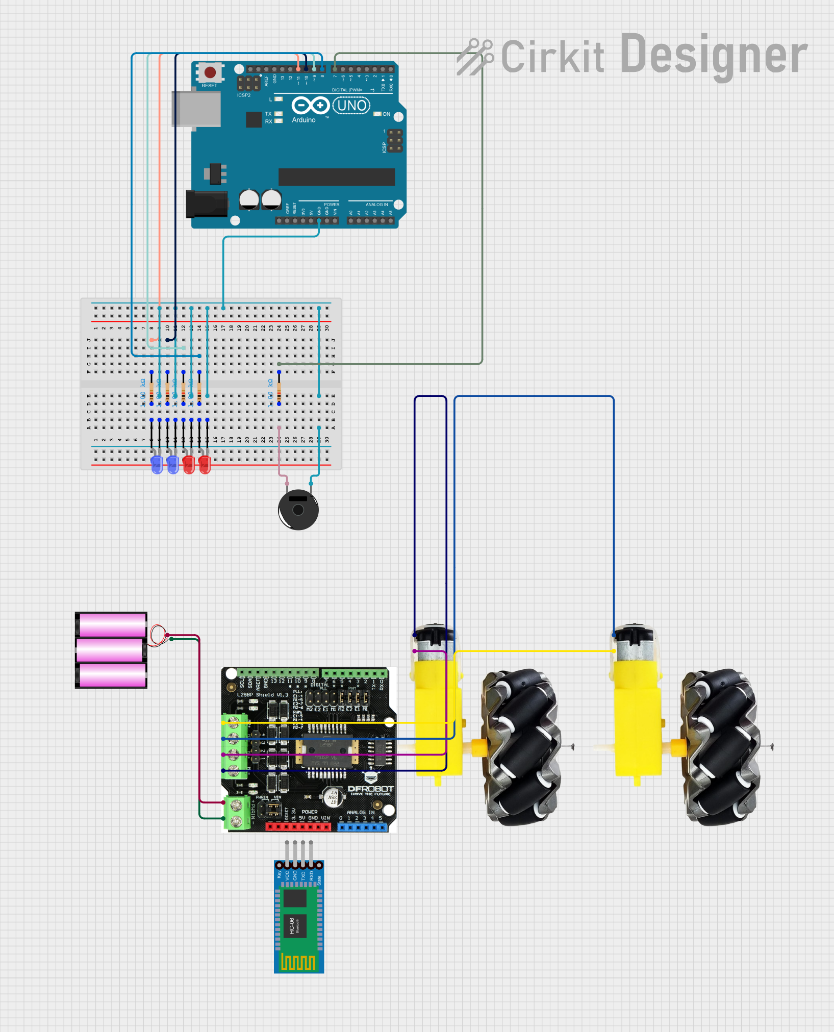
Circuit Documentation
Summary
This circuit is designed to control a set of motors and LEDs using an Arduino UNO and an L298P drive shield. The circuit also includes a piezo buzzer and a Bluetooth module for additional functionalities. The motors are controlled to move forward, backward, left, and right based on serial commands. The LEDs are used for visual indications, and the piezo buzzer is used for sound alerts.
Component List
Motor and Wheels
- Description: Motor and wheel assembly for movement.
- Pins: VCC, GND
L298P Drive Shield
- Description: Motor driver shield for controlling motors.
- Pins: B-, B+, A-, A+, GND, VIN
Battery 12V
- Description: Power source for the circuit.
- Pins: +, -
Resistor (1000 Ohms)
- Description: Current limiting resistor.
- Pins: pin1, pin2
LED: Two Pin (Red)
- Description: Red LED for visual indication.
- Pins: Cathode, Anode
LED: Two Pin (Blue)
- Description: Blue LED for visual indication.
- Pins: Cathode, Anode
Arduino UNO
- Description: Microcontroller for controlling the circuit.
- Pins: UNUSED, IOREF, Reset, 3.3V, 5V, GND, Vin, A0, A1, A2, A3, A4, A5, SCL, SDA, AREF, D13, D12, D11, D10, D9, D8, D7, D6, D5, D4, D3, D2, D1, D0
Piezo Buzzer
- Description: Buzzer for sound alerts.
- Pins: pin 1, pin 2
Bluetooth HC-06
- Description: Bluetooth module for wireless communication.
- Pins: VCC, GND, TXD, RXD
Wiring Details
Motor and Wheels
Motor 1:
- VCC connected to L298P Drive Shield A+
- GND connected to L298P Drive Shield A-
Motor 2:
- VCC connected to L298P Drive Shield B+
- GND connected to L298P Drive Shield B-
L298P Drive Shield
- B- connected to Motor 2 GND
- B+ connected to Motor 2 VCC
- A- connected to Motor 1 GND
- A+ connected to Motor 1 VCC
- GND connected to Battery 12V -
- VIN connected to Battery 12V +
Battery 12V
-
- connected to L298P Drive Shield VIN
-
- connected to L298P Drive Shield GND
Resistors
Resistor 1:
- pin1 connected to LED (Blue) Anode
- pin2 connected to Arduino UNO D11
Resistor 2:
- pin1 connected to LED (Red) Anode
- pin2 connected to Arduino UNO D10
Resistor 3:
- pin1 connected to LED (Red) Anode
- pin2 connected to Arduino UNO D9
Resistor 4:
- pin1 connected to LED (Blue) Anode
- pin2 connected to Arduino UNO D8
Resistor 5:
- pin1 connected to Piezo Buzzer pin 2
- pin2 connected to Arduino UNO D7
LEDs
Red LED 1:
- Anode connected to Resistor 2 pin1
- Cathode connected to Arduino UNO GND
Red LED 2:
- Anode connected to Resistor 3 pin1
- Cathode connected to Arduino UNO GND
Blue LED 1:
- Anode connected to Resistor 1 pin1
- Cathode connected to Arduino UNO GND
Blue LED 2:
- Anode connected to Resistor 4 pin1
- Cathode connected to Arduino UNO GND
Arduino UNO
- D11 connected to Resistor 1 pin2
- D10 connected to Resistor 2 pin2
- D9 connected to Resistor 3 pin2
- D8 connected to Resistor 4 pin2
- D7 connected to Resistor 5 pin2
- GND connected to LEDs and Piezo Buzzer pin 1
Piezo Buzzer
- pin 1 connected to Arduino UNO GND
- pin 2 connected to Resistor 5 pin1
Bluetooth HC-06
- VCC connected to 5V
- GND connected to GND
- TXD and RXD not connected in this documentation
Code Documentation
Arduino UNO Code
#define PIEZO_PIN 7
#define RED_LED_PIN_1 11
#define RED_LED_PIN_2 10
#define BLUE_LED_PIN_1 9
#define BLUE_LED_PIN_2 8
#define POTENTIOMETER_PIN A0

void setup() {
  pinMode(PIEZO_PIN, OUTPUT);
  pinMode(RED_LED_PIN_1, OUTPUT);
  pinMode(RED_LED_PIN_2, OUTPUT);
  pinMode(BLUE_LED_PIN_1, OUTPUT);
  pinMode(BLUE_LED_PIN_2, OUTPUT);

  Serial.begin(9600);
}

void loop() {
  runSirenAndLEDs();
}

void runSirenAndLEDs() {
  for (int i = 0; i < 350; i++) {
    digitalWrite(PIEZO_PIN, HIGH);
    digitalWrite(RED_LED_PIN_1, HIGH);
    digitalWrite(RED_LED_PIN_2, LOW);
    digitalWrite(BLUE_LED_PIN_1, HIGH);
    digitalWrite(BLUE_LED_PIN_2, LOW);
    delay(1);
    digitalWrite(PIEZO_PIN, LOW);
    delay(1);
  }
  delay(50);

  for (int i = 0; i < 150; i++) {
    digitalWrite(PIEZO_PIN, HIGH);
    digitalWrite(RED_LED_PIN_1, LOW);
    digitalWrite(RED_LED_PIN_2, HIGH);
    digitalWrite(BLUE_LED_PIN_1, LOW);
    digitalWrite(BLUE_LED_PIN_2, HIGH);
    delay(2);
    digitalWrite(PIEZO_PIN, LOW);
    delay(2);
  }
}
L298P Drive Shield Code
#include <AFMotor.h>

AF_DCMotor leftMotor(1);
AF_DCMotor rightMotor(2);

#define BLUE_LED 3
#define RED_LED 4

void setup() {
  leftMotor.setSpeed(200);
  rightMotor.setSpeed(200);

  pinMode(BLUE_LED, OUTPUT);
  pinMode(RED_LED, OUTPUT);

  Serial.begin(9600);
}

void loop() {
  if (Serial.available()) {
    char command = Serial.read();

    switch (command) {
      case 'F':
        leftMotor.run(FORWARD);
        rightMotor.run(FORWARD);
        break;

      case 'B':
        leftMotor.run(BACKWARD);
        rightMotor.run(BACKWARD);
        break;

      case 'L':
        leftMotor.run(BACKWARD);
        rightMotor.run(FORWARD);
        break;

      case 'R':
        leftMotor.run(FORWARD);
        rightMotor.run(BACKWARD);
        break;

      case 'S':
        leftMotor.run(RELEASE);
        rightMotor.run(RELEASE);
        break;

      case 'P':
        for (int i = 0; i < 5; i++) {
          digitalWrite(BLUE_LED, HIGH);
          delay(200);
          digitalWrite(BLUE_LED, LOW);
          digitalWrite(RED_LED, HIGH);
          delay(200);
          digitalWrite(RED_LED, LOW);
        }
        break;

      default:
        break;
    }
  }
}
Bluetooth HC-06 Code
void setup() {
  // put your setup code here, to run once:
}

void loop() {
  // put your main code here, to run repeatedly:
}
Battery 12V Code
void setup() {
  // put your setup code here, to run once:
}

void loop() {
  // put your main code here, to run repeatedly:
}